


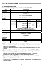
11
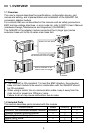
5. LOADING AND INSTALLATION
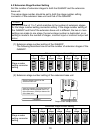
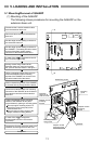
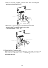
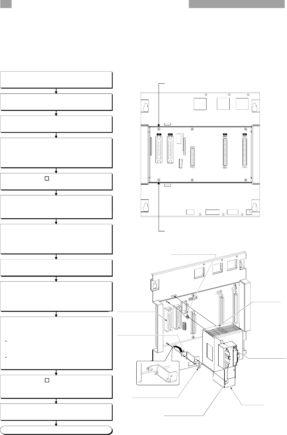
5.1 Mounting/Removal of QA6ADP
(1) Mounting of the QA6ADP
The following shows procedures for mounting the QA6ADP on the
extension base unit.
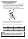
Mount a board fixing screw of the QA6ADP
to a screw hole (A) at top left of the board.
Connect an extension base unit mounting
connector of the QA6ADP to the IN side of
an extension connector of the extension
base unit.
Tighten the adapter module mounting
screws of the QA6ADP at two parts
(top and bottom), placing a mounting guide.
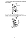
Mount an upper mounting screw to a
board fixing screw (at top left) of the
extension base unit.
Mount a lower mounting screw to the
adapter module mounting bracket.
In case of the A5 B, connect the
disconnected lead of the FG terminal
(right side).
Connect the Q series extension cable to the
QA6ADP and the upper/lower base unit.
Disconnect the A series extension cable
from the extension base unit.
Remove a base cover from the extension
base unit.
Set the stage number setting connector of
the extension base unit.
In case of the A5 B, disconnect a lead of
the FG terminal (right side).
Among screws fixing a board of the
extension base unit, remove two at the
left. (Screws A and B shown in the figure.)
Set the stage number setting connector of
the QA6ADP. (The setting should be same
as that of the stage number setting
connector of the extension base unit.)
Completed
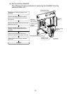
A)
B)
QA6ADP
Board fixing screw
Adapter module
mounting
bracket
Mounting
guide
Adapter module
mounting
screw
Adapter module
mounting screw
Extension
base unit IN
side connector
Utilize a mounting bracket fixing screw to
mount the adapter module mounting
bracket of the QA6ADP into a screw hole
(B) at the bottom left of the board.
M
ounting bracket
fixing screw