


POWER AMPLIFIER OWNER’S MANUAL
8
9
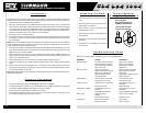
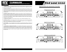
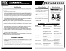
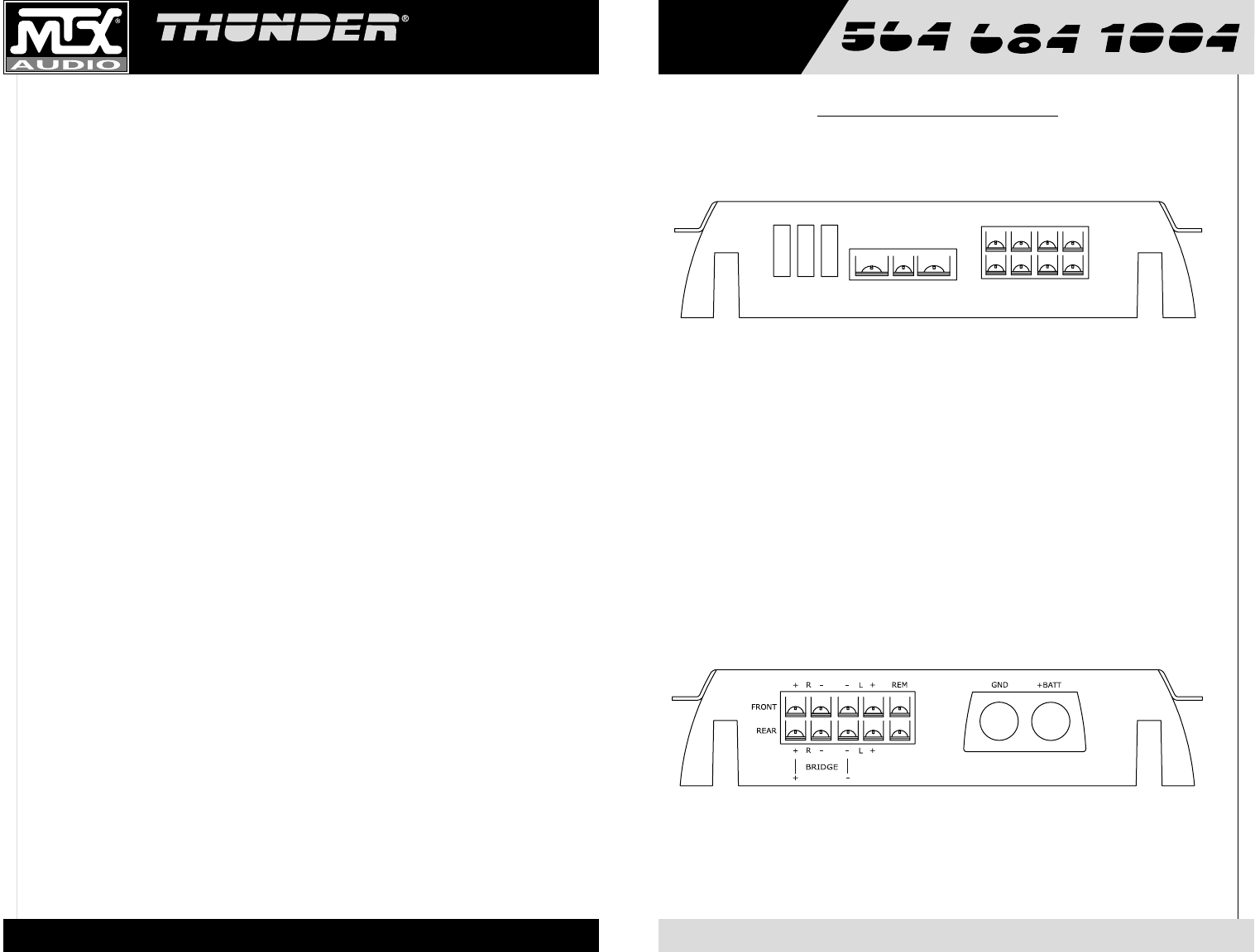
1. Fuses - For convenience, all amplifiers utilize ATC type fuses. For continued protection in the event that
a fuse blows, replace the fuse only with the same value.
Caution: The power fuses on the amp are for protecting the amp against overdrive. To protect the vehicle’s
electrical system, an additional fuse is required within 18" of the battery on the 12V+ cable.
Thunder564 - 25A x 3
Thunder684 - 35A x 3
Thunder1004 - 150 Amps (not supplied)
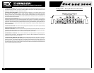
2. Power Terminal – This is the main power input for the amplifier and must be connected directly to the
positive terminal of the car battery for the amplifier to operate properly. See the chart below for recom-
mended cable sizes for each amplifier. Use caution when running this cable through the car. Try to avoid
the input RCA cables, antenna cabling, or other sensitive equipment as the large amount of current flowing
through this cable can induce noise into your system. It is also very important to have a tight connection to
ensure maximum performance.
Thunder564 – 6 - 8 Gauge
Thunder684 – 6 - 8 Gauge
Thunder1004 – 1/0 Gauge only
3. Ground Terminal – A good quality ground is required for your Thunder Amplifier to operate at peak
performance. A short length of cable the same gauge as your power cable should be used to attach the
ground terminal directly to the chassis of the car. Always scrape or sand any painted surfaces to expose
bare metal where the ground wire will attach.
4. Remote Terminal – All Thunder Amplifiers can be turned on by applying 12 volts to this terminal.
Typically this voltage is supplied by a wire from the source unit marked “remote” or “electric antenna”.
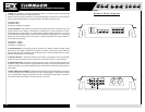
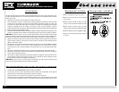
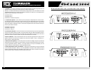
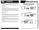
5. Speaker Terminals – As shown in the wiring diagrams, be sure to observe speaker polarity through
the system. Failing to wire the speakers in proper phase could result in a loss of bass response and/or poor
overall sound quality. Caution: Thunder amplifiers are not recommended for loads below 2 ohms stereo or 4
ohms bridged.
6. Power LED (top of heatsink)- A lighted LED indicates that power has been applied to the amplifier.
+12V from the battery to the +BATT terminal and +12V from a switched ignition or remote lead from a head
unit. An unlighted LED indicates power has been removed or the amplifier has overheated. In the case of
the overheat condition, the amplifier will turn back on after it cools down.
Output Panel Layout