


5. Stereo Gain Control – This feature is used to fine-tune the input sensitivity of the amplifier to the source unit’s
output level.
6. Variable Hi, 12dB / Low, 24dB Mono @ 40Hz–350Hz Crossover – This control allows the user to choose the
exact low pass or high pass frequency range the amplifier will play for the best possible performance. The
upper end of the low pass crossover range can be selected from 40Hz–350Hz at 24dB per octave with a mono
output. The lower end of the high pass crossover range can be selected from 40Hz-350Hz at 12dB per octave
with a stereo output.
7. Quasi Parametric EQ - This one band equalizer provides individual frequency and +/-12dB gain adjustment
controls. Any frequency from 30Hz to 80Hz can be chosen and boosted up to 12dB.
8. A.R.C. – The Active Resonance Control (A.R.C.) is a level adjustment that reduces the resonant frequencies
inside the vehicle to improve the midrange sound quality. Turn this control either clockwise or counter-
clockwise until the vocals of the music are up-front and centered in the vehicle. The midrange sound should
be smooth and detailed.
9. Remote Subwoofer Level Control (Remote Gain) – This port allows the use of the optional “remote level
control”. The Remote Subwoofer Control is a bass control module that can be installed in any location within
the vehicle for remote adjustments.
10. StreetWires Connectors – All MTX amplifiers include StreetWires connectors for efficient current and
maximum voltage transfer.
11. Speaker Connection – These output terminals are individually labeled for proper speaker connections. When
bridging the amplifier, use the left positive terminal and the right negative terminal only. Warning, do not
bridge the amplifier with an impedance lower than 4 ohm.
12. Power Terminals – This is the main power connection for the amplifier. The power and ground wire size
should be the same gauge.
• GND – The ground wire from this connection must be attached to bare metal on the vehicle. The distance
to the ground should be as short as possible and no more than 18”.
• REM – To turn the amplifier on/off, this terminal must be connected to the source unit’s “remote or electric
antenna” wire.
• +12V – The power wire from this connection must be attached to the positive side of the vehicle battery.
• CAP+ - Capacitor Positive Input - The ideal connection point for the positive side of the capacitor to
increase the amplifier’s performance.
• CAP- - Capacitor Negative Input - The ideal connection point for the negative side of the capacitor to
increase the amplifier’s performance.
Before Starting
MTX recommends that you have your new Thunder amplifiers installed by an authorized MTX retailer, preferably
MECP certified. If you do decide to do it yourself, make sure you have read the instructions carefully and have
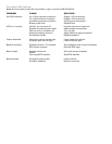
the following tools:
• Electric drill • Phillips bit or screwdriver
• 1/8” bit • Wire cutters/crimpers
• Safety glasses • X-Acto knife
Disconnect the vehicle’s negative battery connection. Any deviation from the recommended connection
procedures may cause serious damage to the amplifier, speakers, and/or vehicle electrical system. Please
double check the connections before turning the system on.
Installation
Mounting
Place your Thunder amplifier at the predetermined mounting location. Use a felt pen to mark the exact position
of the mounting holes on the mounting surface. Set the amplifier aside. With a sharp, precise blade cut small
circles in the carpet and padding around the four marks denoting your mounting holes to expose the metal
underneath. Use a center punch to make an indentation in the metal to ensure that you drill the exact position
for the screws.
Note: Please use common sense and make sure that all vehicle wires, gas lines, brake lines, etc. are clear and will
not interfere with the installation. ALWAYS WEAR PROPER SAFETY GLASSES.