


NEC Display Solutions of America, Inc.
OL-V423 Installation Guide
10 Point Touch Overlay for the V423 Rev 1.0
www.necdisplay.com OL-V423
3
6.0 Integration Procedure
6.1 Place the display face up on a padded surface for overlay integration
6.1.1 Note that if the unit is already mounted, removing the unit and placing it face up is optional;
integration of the touch screen can also be done while the display is mounted
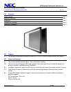
6.2 Remove bottom right corner screw from the factory bezel as shown.
6.3 Remove additional bottom screw
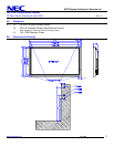
6.4 Remove two (2) screws located in the top of the factory bezel similar
to the bottom screw removal in steps 6.2 and 6.3
6.4.1 Note that only these four (4) screws should be removed. The
other screws are used to keep the bezel secured to the body
of the display
6.5 Remove the IR touch screen overlay from packing and verify contents
of kit parts.
6.6 Clean inside surface of the glass.
6.6.1 Use a glass cleaner or mild cleaning solution to clean glass.
6.6.2 Spray solution onto clean soft cloth then wipe the surface. Spraying cleaning solution directly onto the
monitor may damage the unit.
6.6.3 Use circular motion to avoid smudges and streaks.
6.6.4 DO NOT USE any chemical solvents such as an Acidic, or Alkali solution.
6.7 With help from a partner, lift the touch frame on the side edges and place over the monitor.
6.8 Ensure the six (6) mounting holes on the touch screen overlay align with the screw holes of the monitor.
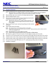
6.9 Install the touch screen overlay using two (2) M3 x 30 flathead Phillips machine screws for the top side
6.10 Install the touch screen overlay using two (2) M3 x 30 flathead Phillips machine screws for the top side
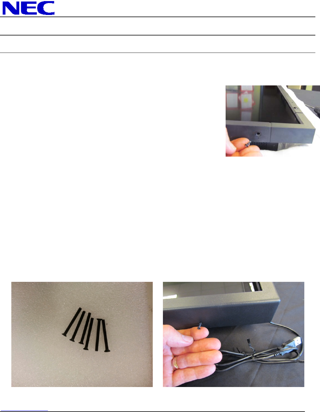
6.11 Connect the touch screen USB cable to the PC / media player providing video to the display.
6.12 Installation is complete.