


cleanly if there is an unseen obstruction
behind the wall. BE VERY CAREFUL
NOT TO SAW THROUGH EXISTING
WIRES, PIPES, OR STRUCTURE. IF
YOU FEEL EXTRA RESISTANCE AS
YOU ARE CUTTING, STOP.
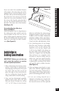
6. If you are cutting into a plaster ceiling,
use masking tape to outline your pen-
ciled circle and use a razor to score the
plaster down to the lath beneath. Then
use a chisel to remove all of the plaster
within the taped outline. To actually cut
the lathe, two methods are used profes-
sionally; sawing with a metal cutting
blade on a sabre saw is the quickest
and the
riskiest. Sawing a lathe with a
sabre saw can easily vibrate plaster off
the ceiling in a completely distant loca-
tion creating more patchwork. If you
have the patience, use a pair of tin snips
to slowly nip away at the lath instead.
There is little risk with this method, it is
just time consuming.
Final Installation in New
or Existing Construction
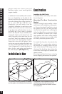
1. If it is possible to lay a batt of insulation
into the ceiling cavity do so. Remember
to use equal amounts of insulation for
each speaker.
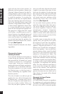
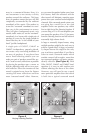
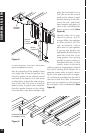
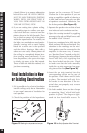
2. Check the position of the Impedance
Jumper on the crossover PC board.
Choose the 4 ohm position if you are
using an amplifier capable of drawing a
4 ohm load and you have only one pair
of speakers connected. Otherwise, use
the 8 ohm position
(See Figure 15).
3. Separate the speaker wire so that at least
two inches of each conductor are free.
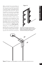
4. Open the no-strip terminal by applying
pressure to the red and black levers until
an audible “click” is heard.
5. Insert one unstripped wire fully into the
black and one into the red terminal. Pay
attention to the markings on the wire.
Each speaker must be connected to the
amplifier in the same way. If unsure,
see “Speaker Phase” located on the fol-
lowing page. Squeeze the red and black
levers until they click signifying that
they have locked into the wire. Check
to make sure that the knife assembly
inside the no strip connector has prop-
erly pierced the wire
(See Figure 16).
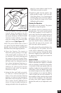
6. Insert the no strip terminal into the
corresponding socket on the rear of
the speaker. Push it down until it locks
in place. The terminal will only fit in
the socket in one direction. If the ter-
minal does not properly seat, reverse
the terminal
7. On both models, there are four clamps
or mounting “dogs” which hold each
speaker in place. The dogs are tight-
ened via four front-baffle screws. To
15
Final Installation in New or Existing Construction
Figure 16 No-Strip Speaker Wire Terminal.
Figure 15 Setting the Impedance Jumper.