


1996 Jan 08 11
Philips Semiconductors Product specification
2 × 40 W/2 Ω stereo BTL car radio
power amplifier with diagnostic facility
TDA8560Q
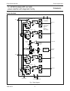
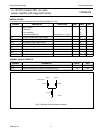
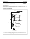
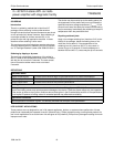
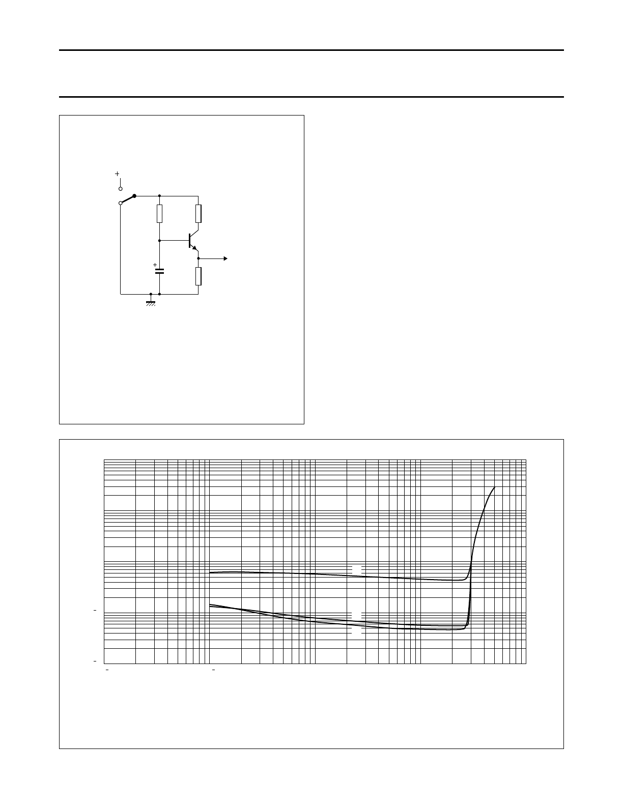
Fig.7 Mode select switch circuitry.
handbook, halfpage
100 kΩ
MGA708
47 µF
10 kΩ 10 kΩ
mode
select
switch
V
P
Diagnostic output
Special care must be taken in the printed-circuit board
layout to separate pin 12 from pin 1 and pin 13, to
minimize the crosstalk between the diagnostic output and
the inputs.
Mode select switch
To avoid switch-on plops, it is advised to keep the amplifier
in the mute mode during >100 ms (charging of the input
capacitors at pin 1 and pin 13).
The circuit in Fig.7 slowly ramps up the voltage at the
mode select switch pin when switching on and results in
fast muting when switching off.
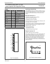
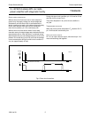
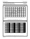
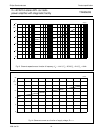
(1) f = 10 kHz.
(2) f = 1 Hz.
(3) f = 100 Hz.
Fig.8 Total harmonic distortion as a function of output power; V
P
= 14.4 V; R
L
=2Ω.
10
2
MGA904
10110
1
10
2
10
1
10
P (W)
o
10
2
1
10
2
THD
(%)
(1)
(2)
(3)