


5
O W N E R ’ S M A N U A L
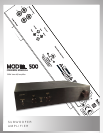
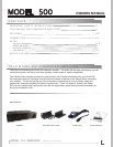
MODEL 500 AMPLIFIER
F E A T U R E S (continued)
2
1
2
3
4
5
6
7
8
9
10
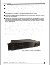
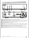
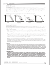
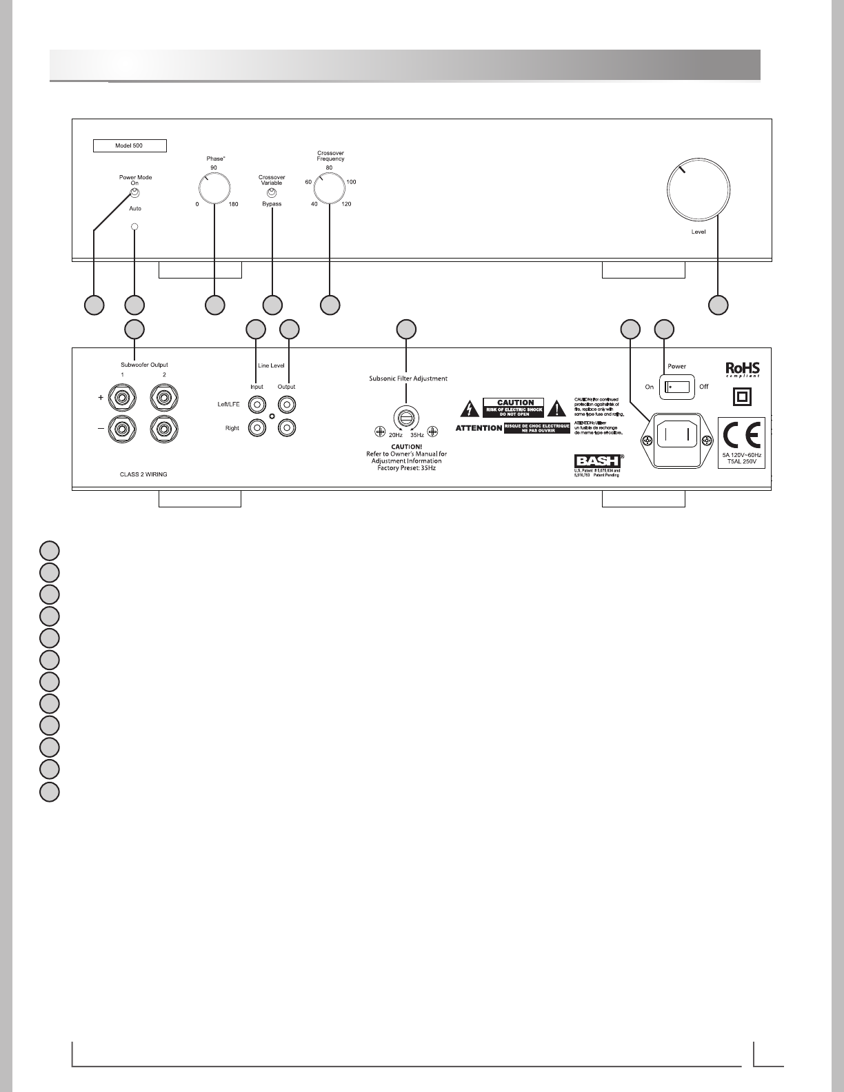
Power Mode Switch – Selects if amplier power is signal activated; Auto=Signal Sensing, On=Bypassed (Amp ON)
Power and Standby Mode Indicator – Off=No Power; Blue=On; Red=Standby
Phase Control – Adjusts relative alignment of output signal with respect to the input; 0o=In Phase, 180o=Out of Phase
Crossover Bypass Switch – Selects if internal crossover (low pass lter) is active, Variable=Active; Bypass=Inactive
Crossover Frequency Control – Adjusts low pass lter cutoff frequency
Level Control – Adjusts output level to subwoofer
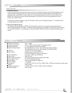
Subwoofer Output – Dual sets of 5-way binding posts provide connection for subwoofer(s); Outputs 1 & 2 are parallel
Line Level Input – Input connection for RCA Line Level signals from processor or preamp; Includes LFE & Sub signals
Line Level Output – Input signal is passed to these jacks to allow multiple connections without the use of Y-cables
Subsonic Filter Adjustment – Adjustment to determine lower frequency limit of amplication
Power Input Receptacle and Fuse Holder – IEC 2-conductor 120V receptacle accepts supplied IEC power cord
Master (Main) Power Switch – Primary power; On=Power Enabled; OFF=Power disconnected from amplier circuit
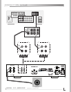
1
63 54
7 8 10 11 129
11
12