


6 © 2007 directed electronics—all rights reserved
Internal Crossover
The crossover section of the Orion Cobalt CO300.2 and CO600.2 amplifiers is continuously vari-
able and extremely flexible.
When using Orion Cobalt loudspeakers, minor deviations from the recommended frequency
ranges can provide superior results depending on your speaker locations and your vehicle
acoustics. Setting crossover frequencies higher than recommended will not cause damage and
may provide superior sonic results depending on your system's performance goals. Refer to your
loudspeaker owner's manual for assistance in choosing the proper crossover frequencies for
your system.
Low-Pass Crossover
The low-pass crossover is active with a 2nd order (12dB per octave) slope. The low-pass crossover
is continuously variable from 50Hz to 500Hz.
High-Pass Crossover
When the switch is to the left (FULL position), the high-pass crossover is bypassed. When the
switch is to the right (HPF position), the high-pass crossover is active. The high-pass crossover is
continuously variable from 50Hz to 500Hz.
AMPLIFIER WIRING
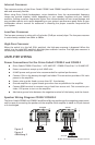
Power Connections for the Orion Cobalt CO300.2 and CO600.2
● Orion Cobalt CO300.2 Fuse Size: 1 x 25 AMP ATC / CO600.2 Fuse Size: 2 x 20 AMP ATC
● Power connections accept up to 4 AWG wire.
● 4 AWG power and ground wire recommended for optimal performance.
● Connect 12V+ to the battery through fuse holder. This connection provides +12V main
power to the amplifier.
● Power wire must be fused no more than 18" from battery.
● Ground amplifier to a good chassis ground as close as possible to the amplifier.
● Connect REM terminal to remote turn-on lead from source unit. This connection pro-
vides +12V power to turn-on the amplifier.
● Add extra ground wire between the negative terminal of the battery and the chassis.
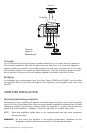
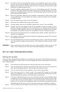
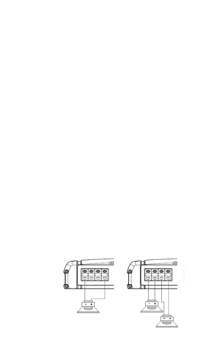
Speaker Wiring Diagram CO300.1/CO600.2
The Orion Cobalt CO300.2 and CO600.2 amplifiers offer two positive and two negative output termi-
nals for ease of connecting the speakers to the amplifier. Each amplifier is stable to 2Ω per channel
or 4 ohm bridged .
Figure 5
Figura 5
Abbildung 5
MASTER
PHASE 0º
SLAVE
PHASE 180º
- - + +
- - + +
- - + +
- - + +
- - ++ - - ++
Bridged Stereo
- - ++
Bridged
Tri-mode
2Ω or 4Ω
2Ω or 4Ω
4Ω or 8Ω
4Ω or 8Ω
4Ω or 8Ω
4Ω or 8Ω
2Ω or 4Ω
2Ω or 4Ω
2Ω or 4Ω
4Ω or 8Ω