


© 2009 Directed Electronics. All rights reserved.
2
C
HARGING
1. Connect the capacitor Negative (-) and battery Negative
(-) to chassis ground of vehicle.
2. Connect one bulb end through fuse to capacitor Positive
(+). It is highly suggested that you place a fuse before the
capacitor.
3. Connect the other bulb end to battery Positive (+).
4. When connection is made, the charging is started.
5. Once a full charge has been reached and the capacitor
module reads the same voltage as the battery. See Fig. 3.
Remove the bulb.
6. Connect the power wire leading to capacitor module to
the positive (+) battery post. Attention, small sparks may
occur. See Fig. 1.
7. Make sure all power and ground connections are made
and secure at the capacitor module.
English
!
!
!
!
S
AFETY
I
NFORMA
TION
CAUTION: To prevent injury and damage to the unit,please read and
follow the instructions in this manual.
CAUTION: If you feel unsure about installing this system yourself,have it
installed by a qualified ORION technician.
CAUTION: Before installation,disconnect the battery negative (
-
) terminal
to prevent damage to the unit,fire and/or possible injury.
CAUTION: Polarity must be observed and maintained during
installation to eliminate the possibility of damaging the
capacitor,the battery,or other associated equipment.
!
I
NSTALLA
TION / M
OUNTING
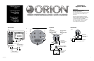
See Figure 1
The ORION Reinforcement Capacitor should be mounted as close to the
amplifier as possible,within 18" (0.5m) of the amplifier,keeping the wire runs
short to reduce voltage losses in the cables. Use the mounting brackets
supplied to secure the capacitor as close to the amplifier as possible.
The capacitor may be mounted in any position;however,care should be taken
to ensure the venting hole on the top is unobstructed at all times.This vent
is a relief valve should the electrical polarity become crossed.
Should the capacitor be damaged, fluid will exit from this vent r
endering
the capacitor useless.
CAUTION
: To prevent damage to the capacitor, do not install in
locations where it will be exposed to water, oil or
mistreatment.
Install in a dry,safe place within 18" (0.5m) of the
amplifier.The positive lead connects to the terminal
marked with a “+” symbol.The negative terminal is
not marked.If these wires are reversed,fluid from inside
the capacitor will leak out of the vent plug on the top.
Do not install a damaged cap.Use care when handling
damaged capacitors,treat them like a fully charged lead
acid battery.
P
OWER
W
IRING
C
ONSIDERATIONS
Installation is simple and straightforward.When installing the capacitor,
we recommend using the same gauge wire as that of the power
connection to the amplifier. Ground the capacitor to the nearest chassis
ground using the same gauge wire as that used for the power connection.
It is strongly recommended the capacitor be fused at the battery.
The fuse value should be the same as that of the power connection to
the amplifier.This fuse should be installed 18" or less from the battery
(See illustration). If the capacitor is to be used in a multi-amp system,
a power distribution block may be used between the capacitor and the
amplifiers. It should be wired using the same gauge wire as that of the
main system.
The posi
tive side of the capacitor will be connected to the positive side
of the amplifier’s power connection (B+).
CAUTION: Do Not Overtighten Screws! Stripped or broken terminals
are NOT covered by the warranty
!
English
D
IGITAL ST
A
TUS
C
AP
F
EATURES
See Figure 2
1. Negative Terminal – Connect to chassis ground.
2. Reverse Voltage Warning – A buzzer will sound if the capacitor is
connected backwards.Ensure that the Positive (+) and Negative (-) leads
are connected correctly.
3. Positive Terminal – Connect to Positive (+) side of vehicle's battery.
4. Voltage Indicator – With the system turned on, the display will show
the DC volts at the capacitor.
Auto Turn-On – Turns on the display during standard operation (voltage
fluctuation).After 5 minutes of non-use (no fluctuation) automatically
reverts to sleep mode.
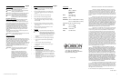
!
WARNING:
To prevent serious personal injury, fire
and/or damage, ensure the capacitor has
been properly discharged before servicing
the vehicle and/or system components.
1. Disconnect the power wire going to the capacitor module from
the battery.
2. Connect one blub end to the capacitor Negative(-) through fuse.
3. Connect the other one bulb end to the capacitor Positive(+).
See Fig. 4.
4. When connection is made, the capacitor is discharging .
5. When the voltage meter readout is close to zero, the capacitor
is discharged .
D
ISCHARGING
SPECIFICATIONS
Rating: 1 farad
(ORC1 or ORC1D)
2 farad hybrid
(ORC2D)
VDC: 1 farad : 20V surge
2 farad : 18V surge
Tolerance: ±10%
Dimensions: 1 farad : 3" x 8.625" (76.2mm x 219mm)
2 farad : 3" x 8.625" (76.2mm x 219mm)
Digital Status Caps add 1.2" (30.5mm) to height
ESR: 1 farad : <1.95m
2 farad : <3.00m
Terminals: 1/4" 28 thread
Tools: 3/16" Allen wrench
Printed in China
1Viper Way, Vista, CA 92081, USA
Phone: (800) 876- 0800 or (760) 598- 6200
Http://www.orioncaraudio.com
C
HARGING
1. Connect the capacitor Negative (-) and battery Negative
(-) to chassis ground of vehicle.
2. Connect one bulb end through fuse to capacitor Positive
(+). It is highly suggested that you place a fuse before the
capacitor.
3. Connect the other bulb end to battery Positive (+).
4. When connection is made, the charging is started.
5. Once a full charge has been reached and the capacitor
module reads the same voltage as the battery. See Fig. 3.
Remove the bulb.
6. Connect the power wire leading to capacitor module to
the positive (+) battery post. Attention, small sparks may
occur. See Fig. 1.
7. Make sure all power and ground connections are made
and secure at the capacitor module.
English
!
!
!
!
S
AFETY
I
NFORMA
TION
CAUTION: To prevent injury and damage to the unit,please read and
follow the instructions in this manual.
CAUTION: If you feel unsure about installing this system yourself,have it
installed by a qualified ORION technician.
CAUTION: Before installation,disconnect the battery negative (
-
) terminal
to prevent damage to the unit,fire and/or possible injury.
CAUTION: Polarity must be observed and maintained during
installation to eliminate the possibility of damaging the
capacitor, the battery, or other associated equipment.
!
I
NSTALLA
TION / M
OUNTING
See Figure 1
The ORION Reinforcement Capacitor should be mounted as close to the
amplifier as possible,within 18" (0.5m) of the amplifier,keeping the wire runs
short to reduce voltage losses in the cables. Use the mounting brackets
supplied to secure the capacitor as close to the amplifier as possible.
The capacitor may be mounted in any position;however,care should be taken
to ensure the venting hole on the top is unobstructed at all times.This vent
is a relief valve should the electrical polarity become crossed.
Should the capacitor be damaged, fluid will exit from this vent r
endering
the capacitor useless.
CAUTION
: To prevent damage to the capacitor,do not install in
locations where it will be exposed to water,oil or
mistreatment.
Install in a dry,safe place within 18" (0.5m) of the
amplifier.The positive lead connects to the terminal
marked with a “+” symbol.The negative terminal is
not marked.If these wires are reversed,fluid from inside
the capacitor will leak out of the vent plug on the top.
Do not install a damaged cap.Use care when handling
damaged capacitors,treat them like a fully charged lead
acid battery.
P
OWER
W
IRING
C
ONSIDERATIONS
Installation is simple and straightforward.When installing the capacitor,
we recommend using the same gauge wire as that of the power
connection to the amplifier.Ground the capacitor to the nearest chassis
ground using the same gauge wire as that used for the power connection.
It is strongly recommended the capacitor be fused at the battery.
The fuse value should be the same as that of the power connection to
the amplifier.This fuse should be installed 18" or less from the battery
(See illustration). If the capacitor is to be used in a multi-amp system,
a power distribution block may be used between the capacitor and the
amplifiers.It should be wired using the same gauge wire as that of the
main system.
The posi
tive side of the capacitor will be connected to the positive side
of the amplifier’s power connection (B+).
CAUTION: Do Not Overtighten Screws! Stripped or broken terminals
are NOT covered by the warranty
!
English
D
IGITAL ST
A
TUS
C
AP
F
EATURES
See Figure 2
1. Negative Terminal – Connect to chassis ground.
2. Reverse Voltage Warning– A buzzer will sound if the capacitor is
connected backwards.Ensure that the Positive (+) and Negative (-) leads
are connected correctly.
3. Positive Terminal – Connect to Positive (+) side of vehicle's battery.
4. Voltage Indicator – With the system turned on,the display will show
the DC volts at the capacitor.
Auto Turn-On – Turns on the display during standard operation (voltage
fluctuation).After 5 minutes of non-use (no fluctuation) automatically
reverts to sleep mode.
!
WARNING:
To prevent serious personal injury, fire
and/or damage, ensure the capacitor has
been properly discharged before servicing
the vehicle and/or system components.
1. Disconnect the power wire going to the capacitor module from
the battery.
2. Connect one blub end to the capacitor Negative(-) through fuse.
3. Connect the other one bulb end to the capacitor Positive(+).
See Fig. 4.
4. When connection is made, the capacitor is discharging .
5. When the voltage meter readout is close to zero, the capacitor
is discharged .
D
ISCHARGING
SPECIFICATIONS
Rating: 1 farad
(ORC1 or ORC1D)
2 farad hybrid
(ORC2D)
VDC: 1 farad :20V surge
2 farad :18V surge
Tolerance: ±10%
Dimensions: 1 farad : 3" x 8.625" (76.2mm x 219mm)
2 farad : 3" x 8.625" (76.2mm x 219mm)
Digital Status Caps add 1.2" (30.5mm) to height
ESR: 1 farad :<1.95m
2 farad :<3.00m
Terminals: 1/4" 28 thread
Tools: 3/16" Allen wrench
Printed in China
1Viper Way, Vista, CA 92081, USA
Phone: (800) 876- 0800 or (760) 598- 6200
Http://www.orioncaraudio.com
C
HARGING
1. Connect the capacitor Negative (-) and battery Negative
(-) to chassis ground of vehicle.
2. Connect one bulb end through fuse to capacitor Positive
(+). It is highly suggested that you place a fuse before the
capacitor.
3. Connect the other bulb end to battery Positive (+).
4. When connection is made, the charging is started.
5. Once a full charge has been reached and the capacitor
module reads the same voltage as the battery. See Fig. 3.
Remove the bulb.
6. Connect the power wire leading to capacitor module to
the positive (+) battery post. Attention, small sparks may
occur. See Fig. 1.
7. Make sure all power and ground connections are made
and secure at the capacitor module.
English
!
!
!
!
S
AFETY
I
NFORMA
TION
CAUTION: To prevent injury and damage to the unit,please read and
follow the instructions in this manual.
CAUTION: If you feel unsure about installing this system yourself,have it
installed by a qualified ORION technician.
CAUTION: Before installation,disconnect the battery negative (
-
) terminal
to prevent damage to the unit,fire and/or possible injury.
CAUTION: Polarity must be observed and maintained during
installation to eliminate the possibility of damaging the
capacitor, the battery, or other associated equipment.
!
I
NSTALLA
TION / M
OUNTING
See Figure 1
The ORION Reinforcement Capacitor should be mounted as close to the
amplifier as possible,within 18" (0.5m) of the amplifier,keeping the wire runs
short to reduce voltage losses in the cables.Use the mounting brackets
supplied to secure the capacitor as close to the amplifier as possible.
The capacitor may be mounted in any position;however,care should be taken
to ensure the venting hole on the top is unobstructed at all times.This vent
is a relief valve should the electrical polarity become crossed.
Should the capacitor be damaged, fluid will exit from this vent r
endering
the capacitor useless.
CAUTION
: To prevent damage to the capacitor,do not install in
locations where it will be exposed to water,oil or
mistreatment.
Install in a dry,safe place within 18" (0.5m) of the
amplifier.The positive lead connects to the terminal
marked with a “+” symbol.The negative terminal is
not marked.If these wires are reversed,fluid from inside
the capacitor will leak out of the vent plug on the top.
Do not install a damaged cap.Use care when handling
damaged capacitors,treat them like a fully charged lead
acid battery.
P
OWER
W
IRING
C
ONSIDERATIONS
Installation is simple and straightforward.When installing the capacitor,
we recommend using the same gauge wire as that of the power
connection to the amplifier.Ground the capacitor to the nearest chassis
ground using the same gauge wire as that used for the power connection.
It is strongly recommended the capacitor be fused at the battery.
The fuse value should be the same as that of the power connection to
the amplifier.This fuse should be installed 18" or less from the battery
(See illustration). If the capacitor is to be used in a multi-amp system,
a power distribution block may be used between the capacitor and the
amplifiers.It should be wired using the same gauge wire as that of the
main system.
The posi
tive side of the capacitor will be connected to the positive side
of the amplifier’s power connection (B+).
CAUTION: Do Not Overtighten Screws! Stripped or broken terminals
are NOT covered by the warranty
!
English
D
IGITAL ST
A
TUS
C
AP
F
EATURES
See Figure 2
1. Negative Terminal – Connect to chassis ground.
2. Reverse Voltage Warning– A buzzer will sound if the capacitor is
connected backwards.Ensure that the Positive (+) and Negative (-) leads
are connected correctly.
3. Positive Terminal – Connect to Positive (+) side of vehicle's battery.
4. Voltage Indicator – With the system turned on,the display will show
the DC volts at the capacitor.
Auto Turn-On – Turns on the display during standard operation (voltage
fluctuation).After 5 minutes of non-use (no fluctuation) automatically
reverts to sleep mode.
!
WARNING:
To prevent serious personal injury, fire
and/or damage, ensure the capacitor has
been properly discharged before servicing
the vehicle and/or system components.
1. Disconnect the power wire going to the capacitor module from
the battery.
2. Connect one blub end to the capacitor Negative(-) through fuse.
3. Connect the other one bulb end to the capacitor Positive(+).
See Fig. 4.
4. When connection is made, the capacitor is discharging .
5. When the voltage meter readout is close to zero, the capacitor
is discharged .
D
ISCHARGING
SPECIFICATIONS
Rating: 1 farad
(ORC1 or ORC1D)
2 farad hybrid
(ORC2D)
VDC: 1 farad :20V surge
2 farad :18V surge
Tolerance: ±10%
Dimensions: 1 farad : 3" x 8.625" (76.2mm x 219mm)
2 farad : 3" x 8.625" (76.2mm x 219mm)
Digital Status Caps add 1.2" (30.5mm) to height
ESR: 1 farad :<1.95m
2 farad :<3.00m
Terminals: 1/4" 28 thread
Tools: 3/16" Allen wrench
Printed in China
1Viper Way, Vista, CA 92081, USA
Phone: (800) 876- 0800 or (760) 598- 6200
Http://www.orioncaraudio.com
LIMITED 90-DAY ACCESSORY/1-YEAR CAPACITOR WARRANTY
This product is sold with a LIMITED 90-day accessory/1-year capacitor
manufacturer’s warranty. Directed Electronics (“Directed”) promises to the original
purchaser that the product (“Product”) will be free from defects in materials and
workmanship under normal use and condition for a period of ninety (90) days for ac-
cessories/ one (1) year for capacitors after the date of purchase. A sales receipt and/
or warranty registration card is required to provide proof of date of purchase of the
Product.
Product defect occurring within the first 90 days for accessories or 1-year
for capacitors after retail purchase by the end consumer will be repaired or replaced
with new or reconditioned part(s), at Directed’s sole election. To obtain warranty
service, the Product must be returned, postage pre-paid addressed to Directed,
along with a legible copy of the receipt and the following information: Consumer’s
name, telephone number and address, authorized dealer/purchase location name and
address and product description. ALL PRODUCTS RECEIVED BY DIRECTED FOR
WARRANTY REPAIR WITHOUT PROOF OF PURCHASE WILL BE DENIED. Note:
This warranty does not cover labor costs for the removal or reinstallation of the
Product. Product must be returned to the following address: ATTN: WARRANTY
DEPARTMENT, Directed Electronics, 1 Viper Way, Vista, CA 92081.
This warranty is non-transferable and does not apply to any Product that
has been modified or used in a manner contrary to its intended purpose, and does
not cover damage to the Product caused by installation or removal of the Prod-
uct. This warranty is VOID if the Product has not been purchased from Directed
or an authorized Directed dealer, or if the Product has been damaged by accident,
unreasonable use, negligence, acts of God, neglect, improper service or other causes
not arising out of defect in materials or construction. This warranty does not cover
the elimination of externally generated static or noise, or any installation problems
related to speakers, accessories, electrical systems, cosmetic damage or damage due
to negligence, misuse, abuse, failure to follow operating instructions, accidental spills
or customer applied cleaners, damage due to environmental causes such as floods,
airborne fallout, chemicals, salt, hail, windstorms, lightning or extreme temperatures,
damage due to accidents, road hazards, fire, theft, loss or vandalism, damage due to
improper connection to equipment of another manufacturer, modification of existing
equipment, or Product which has been opened or tampered with for any reason or
which has been damaged due to alteration or service performed by anyone other
than Directed. This warranty is only valid for sale of Product within the United States
of America. Product sold outside of the United States of America is sold “AS IS,” and
shall have NO WARRANTY, express or implied.
THIS LIMITED WARRANTY IS THE ONLY WARRANTY FOR THIS
PRODUCT. ALL OTHER WARRANTIES, INCLUDING BUT NOT LIMITED TO EX-
PRESS WARRANTY, IMPLIED WARRANTY, WARRANTY OF MERCHANTABILITY,
FITNESS FOR PARTICULAR PURPOSE, AND WARRANTY OF NON-INFRINGE-
MENT OF INTELLECTUAL PROPERTY ARE EXPRESSLY EXCLUDED TO THE
MAXIMUM EXTENT ALLOWED BY LAW, AND DIRECTED NEITHER ASSUMES
NOR AUTHORIZES ANY PERSON TO ASSUME FOR IT ANY LIABILITY IN CON-
NECTION WITH THE SALE OF THE PRODUCT. DIRECTED HAS ABSOLUTELY
NO LIABILITY FOR ANY AND ALL ACTS OF THIRD PARTIES INCLUDING ITS
LICENSED DEALERS OR INSTALLERS. IN NO EVENT WILL DIRECTED BE LIABLE
FOR ANY INCIDENTAL, SPECIAL OR CONSEQUENTIAL DAMAGES (INCLUD-
ING LOSS OF PROFITS). BY PURCHASING THIS PRODUCT, THE CONSUMER
AGREES AND CONSENTS THAT ALL DISPUTES BETWEEN THE CONSUMER
AND DIRECTED SHALL BE RESOLVED IN ACCORDANCE WITH CALIFORNIA
LAWS IN SAN DIEGO COUNTY, CALIFORNIA.
Some states do not allow limitation on how long an implied warranty lasts.
In such states, the limitations or exclusions of this Limited Warranty may not apply.
Some states do not allow the exclusion or limitation of incidental or consequential
damages. In such states, the exclusion or limitation of this Limited Warranty may not
apply to you. This Limited Warranty gives you specific legal rights, and you may have
other rights which vary from state to state.
For more information on Orion products please visit www.orioncaraudio.com
920 0011 2009-11