


© 2008 Directed Electronics. All rights reserved. 8
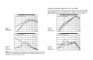
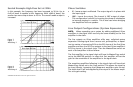
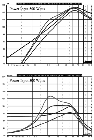
Sealed Example High-Pass Set at 30Hz
In this example, the frequency has been increased to 30 Hz. Up to
6 dB of boost is capable at this frequency. With +6dB of boost, the
woofer has more output down to 23 Hz. The overall usable output is
increased.
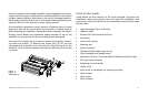
Figure 7
Figura 7
Abbildung 7
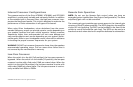
Figure 8
Figura 8
Abbildung 8
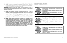
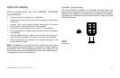
Phase Switches
0° -• leaves output unaffected. The output signal is in phase with
the input signal.
180° -• inverts the output. The channel is 180° output of phase.
This configuration is useful for inverting the phase of subwoofers
to improve staging in a vehicle. This is also used when bridging
two amplifiers into one speaker.
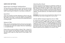
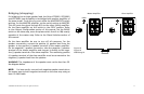
Line Output Configurations (System Expansion)
NOTE: When expanding your system by adding additional Orion
amplifiers in the signal chain use only the same model(s) as the first
amplifier in the chain.
The line outputs on Orion amplifiers offer easy, unlimited system
expansion. Routing signal from a source unit, pre-amplifier, or equal-
izer is a matter of connecting RCAs to the RCA Inputs of the first Orion
amplifier and then the RCA line outputs to the next Orion amplifier’s
RCA line inputs in the signal chain. Then the Master/Slave switch on
each of the amplifiers is set as follows:
The first amplifier in the signal chain will have its Master/Copy switch
set to the MASTER position. In effect this first amplifier will set the
gain for the remainder of the amplifiers in the signal chain.
The remaining amplifiers following in the signal chain will have their
Master/Copy switch set to the Copy position. This allows the signal to
be input directly, bypassing the subsequent amplifiers gain control.
The audio level is set and supplied by the output of the master ampli-
fier at its gain setting.