


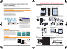
MICRO-IMAGECHECKER
®
A210
•
A110 MultiChecker V2 Series
MICRO-IMAGECHECKER
®
A210
•
A110 MultiChecker V2 Series
10 11
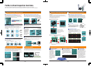
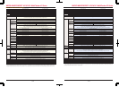
■ A210
•
A110 Multi-checker V2 specifications
A210 Multi-checker V2 A110 Multi-checker V2
64 32
Max. 96 per product type Rotation position adjustment function Max. 48 per product type X-Y position adjustment function
Smart matching = Max. 96 pcs.; Equipped with post-detection ifferential processing function
Matching = 48 per product type
32-bit RISC CPU (high-speed processing version) 32-bit RISC CPU
512 × 480 (pixels) × 256 gradations
Max. 96 per product type Max. 48 per product type
Menu selection using the key emulation function (ver. 2.2 or later).
Max. 96 per product type Max. 48 per product type
Shape: rectangular/polygonal or oval mask Shape: rectangular/polygonal or oval Gray-scale mean value detection/judgement
Change between gray-scale memory/gray-scale through/binary memory (A/B/C/D/E/F)/binary through (A/B/C/D/E/F)/gray-scale NG/binary NG (A/B/C/D/E/F)
8 bit 256 gradations
6 groups of binary processing from the gray-scale memory (upper and lower threshold settings)
Execute All mode: Execute all set checkers
Automatic Switch mode: Change the checker to be executed in accordance with the judgment output result
User-Defined mode: Specify the checker for execution when the start signal is input
Shape: rectangular Binarization adjusts according to changes in the gray-scale data Gray-scale mean value detection/judgement
Sub-pixel accurate multiple detection matching by gray-scale correlation processing
Rotation by raster detection and raster detection position (±30 degrees)
Output = number of detected items/correlation numbers/position/angle teaching registered
changes can be imported from external source smart teaching (A210) = judgement learning function by the smart template
CPU
Frame memory
Operator interface
Monitor display
Processing Gray-scale
Exposure
adjustment
Gray-scale window
Smart matching/
matching
(sub-pixel processing)
Gray-scale edge
detection
(sub-pixel processing)
Feature extraction
Binarization
Number of product types
Execution modes
Inspection
Position/
rotation position
adjustment function
Priority adjustment multi-stage adjustment sequence setting by
matching/gray-scale edge/binary edge or feature detection.
Max. 96 per product type Max. 48 per product type
Scanning method = individual/projection gray-scale filter/width function detection by sub-pixel unit
Detection position = forepoint/forepoint and afterpoint/largest differential/multiple edge
Max. 96 per product type Max. 48 per product type
Shape = rectangular/polygonal or oval mask Shape = rectangular/polygonal or oval
Image filtering Labeling Output values: counter/center of gravity (to one decimal place)/area/shading/width/principle axis angle
Max. 96 per product type Max. 48 per product type
Shape = rectangular/polygonal or oval mas Shape = rectangular/polygonal or oval Image filtering White/black pixel number count/judgement
Max. 96 per product type Max. 48 per product type
Shape = line/mask filter/width functions forepoint edge detection
Max. 96 per product type Max. 48 per product type
Max. 96 per product type Max. 48 per product type
External output (D) register = Max. 96 per product type Internal judgement (R) register = Max. 96 per product type External output (D) register = Max. 48 per product type Internal judgement (R) register = Max. 48 per product type
Shape = straight line/polygonal line/circle or arc Image filters White/black pixel number count/judgement
Sine, cos, absolute differential and projection distance functions four data calculations, arctangent, root, the distance-between-points special substitutions reference to previous data output control
RS232C = 2ch (max.115200bps) Compatible with Matsushita Electric Works PLC FP series
Compatible with Mitsubishi MELSEC A Series/FX Series, Omron C Series PLCs, and Allen-Bradley SLC 500 PLCs (Ver. 2.2 or later)
Input = 11points Output = 14 points Removable screw-down terminal block
Image trigger (timing sensor unnecessary) external sensor timing repeat start
Trap function Image storage function
Display item suppressing function (menu display hide function)
Image suppress function when setting checkers, Image rotation function when setting checkers (A210)
Clearly display reject location, Rotational adjustment angle display (A210), Data Monitor function
Display of image processed with image filter, simple spreadsheet, checker list display
30 screens 8 screens
Save/load function for inspection image (all screens/problem screens)
Store images for reinspection/resetting Windows-PC image save/load function
Focus setup, aperture setup, lighting adjustment, image profile monitor, recommended
threshold level, I/O monitor, enforce output
Double-speed random camera (progressive)/flash/electronic shutter used
Image data and setup data can be saved to a Windows PC using vision Backup Tool Ver.
High-speed random trigger camera (progressive) = ANM831 Standard camera = ANM830A, Composite video (NTSC) input used (however the connection requires one port)
24 V DC less than 0.9 A 24 V DC less than 0.7 A
21
External
interface
Serial
Judgement output
Parallel
Maximum of 8 graphics/type (line, rectangle or circle), and registered images are displayed on the main screen
Marker function
Inspection start
Other
specifications
Display functions
Setup tools Image storage
function
Debugging
Setup help
Moving object inspection
Camera support
Number of support cameras
Operating voltage
Setup data backup
*
Binary window
Binary edge detection
Line
Numerical
calculations
Type data saved in the previous controller of the MICRO-IMAGECHECKER A Series (Ver. 1) cannot be directly restored to V2 using the Vision Backup-Tool. In this case, you will
need the dedicated data conversion software (freeware) to convert the Ver. 1 type data for V2 use. If you require the data conversion software or information about how to use it,
contact your Matsushita Automatic Controls Co. Ltd. representative. You can also download the data converter software from the follwing Web page.
http://www.naisvision.com/j
Conversion data
4 registers, Can quote to numerical conversion, Can convert numerical conversion result to actual distance, Standard distance, No. of pixels, Cooefficient
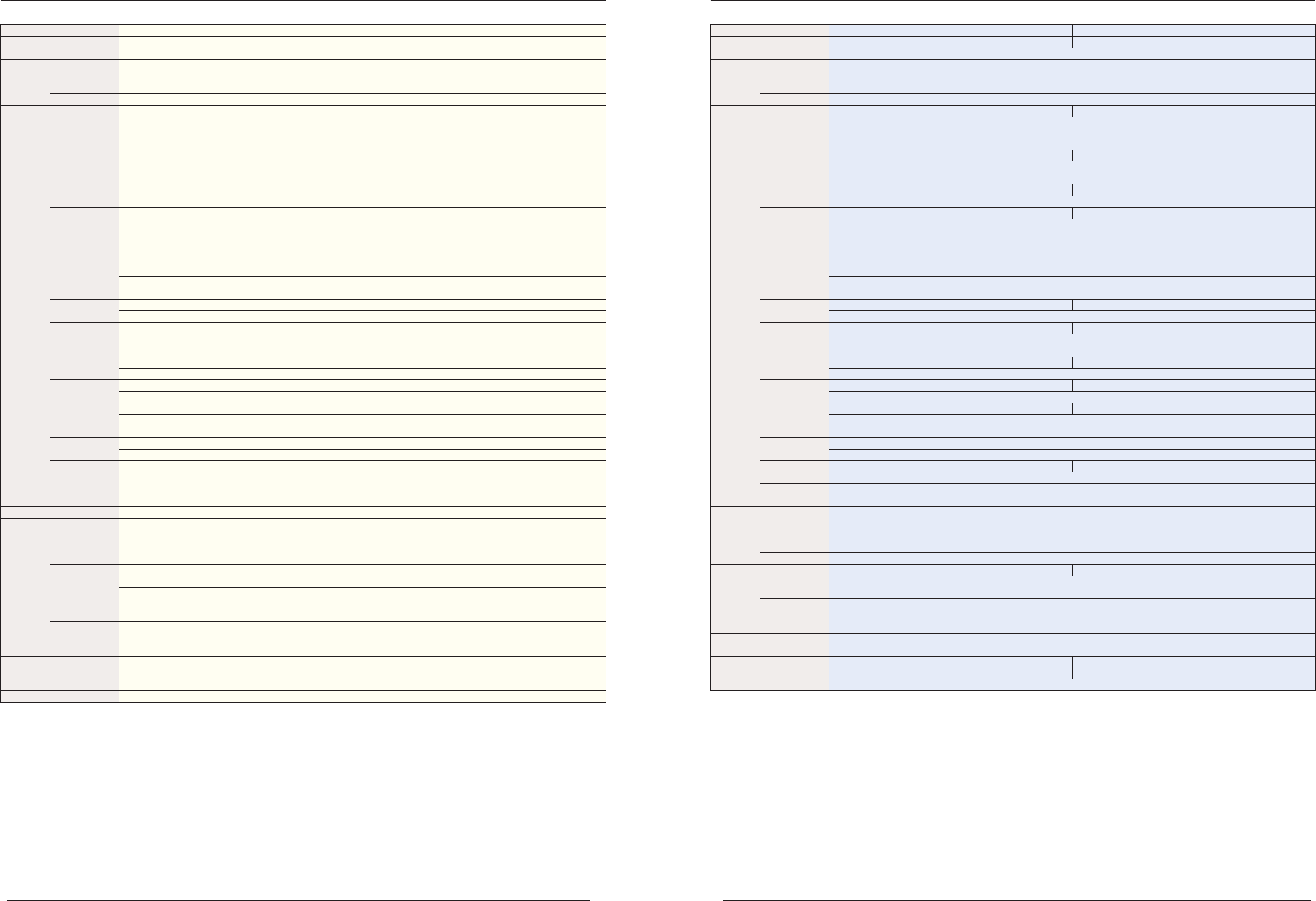
■ A210
•
A110 Multi-checker specifications
A210 Multi-checker A110 Multi-checker
64 32
Max. 32 per product type Rotation position adjustment function Max. 4 per product type
Smart matching = 32 pcs.; Equipped with post-detection ifferential processing function
Matching = 4 per product type
32-bit RISC CPU (high-speed processing version) 32-bit RISC CPU
512 × 480 (pixels) × 256 gradations
Max. 8 per product type Max. 4 per product type
Menu selection by specialized keypad
Max. 32 per product type Max. 16 per product type
Shape: rectangular/polygonal or oval mask Shape: rectangular/polygonal or oval Gray-scale mean value detection/judgement
Change between gray-scale memory/gray-scale through/binary memory (A/B/C/D)/binary through (A/B/C/D)/gray-scale NG/binary NG (A/B/C/D)
8 bit 256 gradations
4 groups of binary processing from the gray-scale memory (upper and lower threshold settings)
—
Shape: rectangular Binarization adjusts according to changes in the gray-scale data Gray-scale mean value detection/judgement
Sub-pixel accurate multiple detection matching by gray-scale correlation processing
Rotation by raster detection and raster detection position (±30 degrees)
Output = number of detected items/correlation numbers/position/angle teaching registered
changes can be imported from external source smart teaching (A210) = judgement learning function by the smart template
CPU
Frame memory
Operator interface
Monitor display
Processing Gray-scale
Exposure
adjustment
Gray-scale window
Smart matching/
matching
(sub-pixel processing)
Gray-scale edge
detection
(sub-pixel processing)
Feature extraction
Binarization
Number of product types
Execution modes
Inspection
Position/
rotation position
adjustment function
Priority adjustment multi-stage adjustment sequence setting by
matching/gray-scale edge/binary edge or feature detection.
Max. 32 per product type
Scanning method = individual/projection gray-scale filter/width function detection by sub-pixel unit
Detection position = forepoint/forepoint and afterpoint/largest differential/multiple edge
Max. 32 per product type Max. 16 per product type
Shape = rectangular/polygonal or oval mask Shape = rectangular/polygonal or oval
Image filtering Labeling Output values: counter/center of gravity (to one decimal place)/area/shading/width/principle axis angle
Max. 32 per product type Max. 16 per product type
Shape = rectangular/polygonal or oval mas Shape = rectangular/polygonal or oval Image filtering White/black pixel number count/judgement
Max. 64 per product type Max. 32 per product type
Shape = line/mask filter/width functions forepoint edge detection
Max. 32 per product type Max. 16 per product type
32 per product type
External output (D) register = Max. 32 per product type Internal judgement (R) register = Max. 32 per product type External output (D) register = Max. 8 per product type Internal judgement (R) register = Max. 8 per product type
Shape = straight line/polygonal line/circle or arc Image filters White/black pixel number count/judgement
4 arithmetic calculations, arctangent, root, the distance-between-points special substitutions reference to previous data output control
Input = 11points Output = 14 points Removable screw-down terminal block
RS232C = 2ch (max.115200bps) Matsushita Electric Works PLC compatible with FP series
Image trigger (timing sensor unnecessary) external sensor timing repeat start
Trap function Image storage function
Display item suppressing function (menu display hide function)
Image suppress function when setting checkers, Image rotation function when setting checkers (A210)
Clearly display reject location, Rotational adjustment angle display (A210)
Numerical calculations results display, Image filtering display function, Accumulated data display, Display list of checkers
32 screens 8 screens
Save/load function for inspection image (all screens/problem screens)
Store images for reinspection/resetting Windows-PC image save/load function
Focus setup, aperture setup, lighting adjustment, image profile monitor, recommended
threshold level, I/O monitor, enforce output
High-speed random trigger camera (progressive)/flash/electronic shutter used
Setup data can be saved to a Windows PC using the Vision Backup-Tool Ver. 2
Double-speed random camera (progressive) = ANM831 Standard camera = ANM830A, Composite video (NTSC) input used (however the connection requires one port)
24 V DC less than 0.9 A 24 V DC less than 0.7 A
21
External
interface
Judgement output
Conversion data
Parallel
Serial
—
Marker function
Inspection start
Other
specifications
Display functions
Setup tools Image storage
function
Debugging
Setup help
Moving object inspection
Camera support
Number of support cameras
Operating voltage
Setup data backup
*
Binary window
Binary edge detection
Line
Numerical
calculations
Type data saved in the previous controller of the MICRO-IMAGECHECKER A Series (Ver. 1) cannot be directly restored to V2 using the Vision Backup-Tool. In this case, you will
need the dedicated data conversion software (freeware) to convert the Ver. 1 type data for V2 use. If you require the data conversion software or information about how to use it,
contact your Matsushita Automatic Controls Co. Ltd. representative.
4 registers, Can quote to numerical conversion, Can convert numerical conversion result to actual distance, Standard distance, No. of pixels, Cooefficient
11/2004
11/2004