Setup help function
Global application
Quantitative support for settings that once relied on intuition.
English-Japanese interchange and CE certification
With the setup help function, focusing, brightness adjustment, exposure
adjustment, binary level settings, and other adjustments that used to be
performed by the operator's professional experience, these adjustments can now
be performed quantitatively. Equipped with an input monitor and test output
functions, connections to external equipment are also greatly simplified. Great
savings can be made in debugging and adjustment by the combination of the trap
function, which halts inspection when an error is found, and the image storage
and spreadsheet functions.
Displays for the one controller can be set to either English or Japanese to allow
use in a great number of countries around the globe. The controller and high-
speed random trigger camera are standard products and are certified with CE
markings.
However, it is not possible to directly restore type data backed up
using Vision Backup-Tool with the previous product (Ver. 1) to V2
(Ver. 2). In this case, use the dedicated data conversion software
(freeware) to convert the Ver. 1 type data for V2 use, then transfer it
to V2 and perform a backup again. If you require the data conversion
software, contact your Matsushita Automation Controls Co. Ltd.
representative.
*
Excellent maintenance characteristics and
global compatibility.
Powerful support for startup and maintenance and designed for worldwide use.
8
9
■ Vision Backup-Tool Ver.2
The product data created with the MICRO-IMAGECHECKER A
series and the image data stored in the controller can be stored
on a PC using Windows.
Stored data can be restored to the A series controller.
Image storage function (A210, A110)
Storing up to 30 pictures* of fault occurrences in its memory, it possible for
analyzing error causes and making adjustments. When setting up the
equipment, inspection images are stored and can be used when making new
adjustments and changes. Moreover, the stored images can be used for testing.
Also, using special software, image data and inspection conditions can be
stored, and then faults can be analyzed and adjustments made at any location
using e-mail. Furthermore, the location of all errors are clearly displayed and
illuminated so that they can be seen at a glance.
The A Series can store up to 30 defect images, and with the dedicated software
tools you analyze the cause of defects at remote locations using e-mail.
OK OKNG NG
30
images
NG
ENTER
A
C
B
Image storage
Readjustment and
re-testing analysis
takes place using
the stored images.
Can be stored
to hard disk or
e-mailed using
special software
Focus adjustment Aperture adjustment
Binarization adjustment
Japanese
EMC(
89/336/EEC)
EN50081-2:1993
EN50082-2:1995
Video game
style control
English
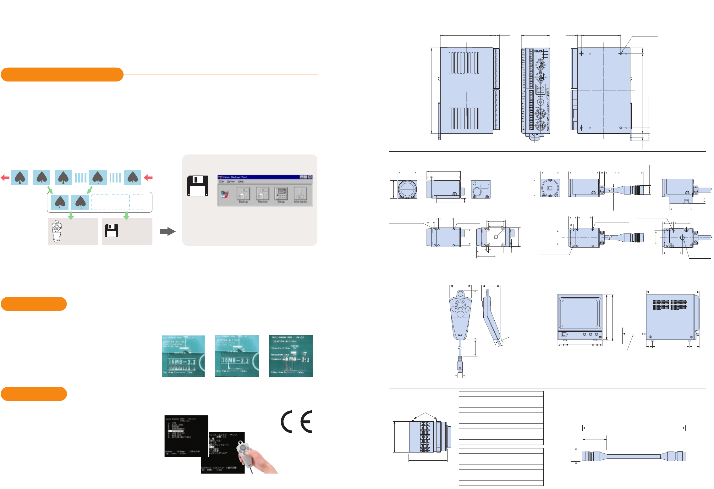
■ Dimensions (unit: mm)
● A110/A210 Controller
ANMA212V2/ANMA212
ANMA112V2/ANMA112
ANM831
● Double-speed random camera: C mount
ANM8520
Ȟ
ANM8520
Ȟ
CE
Ȟ
: Length of cable
AUGPBM910 (100 V AC)
● Operating key pad ● Monitor (Panasonic: GPBM910)
ANM84303/ANM84303CE
ANM840
ȞȞ
A
ANM840
ȞȞ
ACE
Ȟ
: Length of cable
● Lens
● Camera cable
The A110 does not have a
camera B port
Allow 80 mm behind the monitor for wiring
and heat radiation.
Monitor input/output uses a BNC terminal.
Note:
Approx. 80 mm, including
cable connection
Mounting screws (locked lens only)
2-M3(depth 4mm)
4-M3
Without mounting bracket With mounting bracket
(depth 2.5mm)
13
19
24.5±0.6
24.5±0.6
26±0.6
31
2.5
31
1/4-20UNC
(depth 9mm)
(19)
(31.3)
A
B
Panasonic
V-HOLD BLIGHT
CONTRAST
Video Monitor GP-BM
220
228
148
36.5
36.5
259
180
50
29
ENTER
A
B
C
ø11.5
*A
*A: Approximated length of cable for keypad used
The cable is slightly shorter on keypads with
CE marking.
*B: Approximated length of cable used
The cable is slightly shorter on keypads with
CE marking.
124.6
54.4
18
46
(43)
ø14.7
*B
MICRO-IMAGECHECKER
®
A210
•
A110 MultiChecker V2 Series
74
(
10
)
40
55
(
5.5
)
4-M3 depth1.5
(
8
)
120
104
(
9.5
)
(
5.5
)
10
54.5
46.5
8
31
29
(3.25)
*A210 = 30 image, A110 = 8 images
CS Mount lens
AB
ANM8808
ANM88081
ANM8804
ANM88041
ANM8828
ANM88281
=34
=31
=34
=31
=34
=31
f=8
f=8
f=4
f=4
f=2.8
f=2.8
35
35
41
40
38
37.5
φ
φ
φ
φ
φ
φ
C Mount lens
AB
ANB842
ANB843(L)
ANB845N(L)
ANB846N(L)
ANB88161
ANB88251
ANB847(L)
ANM8850
ANM88501
=48
=42
=30
=30
=30.5
=30.5
=48
=27.5
=30.5
f=6.5
f=8.5
f=16
f=25
f=16
f=25
f=50
f=50
f=50
42
40
33
37.3
25
25.5
48
38.5
38.5
φ
φ
φ
φ
φ
φ
φ
φ
φ
32.15
10.5±0.2
38
23±0.2
26±0.2
(
43
)
49.5 *1)
*1) ANM832: 3000
*1) ANM832CE: 2780
*1) ANM83203: 300
8
1/4-20UNC
depth 10mm
28±0.218.15
2-M3(depth 7mm)
8
(
depth 14.7
)
2-M3
(
depth 4mm
)
14
4-M3(depth 2.5mm)
24.5±0.2
29
31
Without mounting bracket With mounting bracket
ANM832/ANM832CE/ANM83203
● CS mount camera: CS mount
(
depth 6.7
)
–10
–10
–10
+80
+80
+40
11/2004
11/2004


