


APPENDICES CM9760-SAT 5-1
SECTION 5 APPENDICES
APPENDIX I COMMUNICATION AND CONNECTION TUTORIAL ................................................................................................5-1
APPENDIX II REMOTE KEYPAD CONNECTION............................................................................................................................5-2
APPENDIX III KEYPAD DEFINITIONS AND TEMPLATES ...............................................................................................................5-5
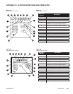
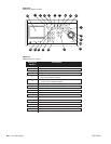
APPENDIX IV MODELS AND ASSOCIATED EQUIPMENT ..............................................................................................................5-7
APPENDIX V DEFAULT RESET ASSIGNMENT ..............................................................................................................................5-7
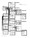
APPENDIX VI CONNECTOR PINOUT LISTINGS FOR ALL CONNECTORS ..................................................................................5-9
APPENDIX I – COMMUNICATION AND CONNECTION TUTORIAL
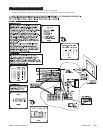
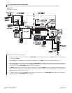
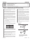
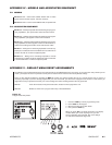
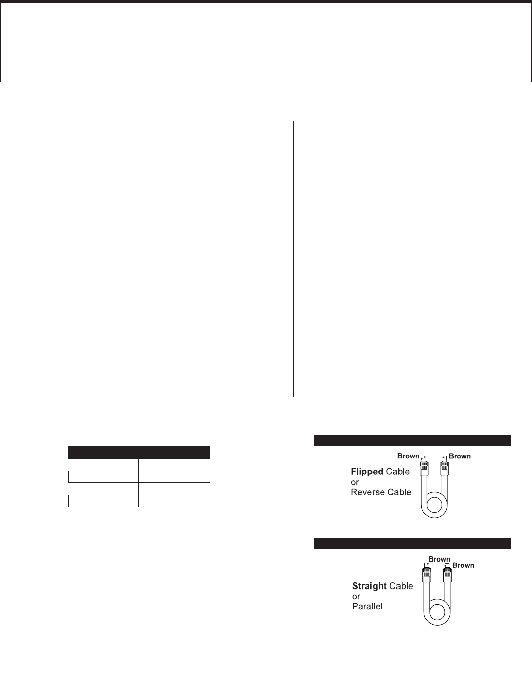
Figure 5-1
Identifying Cables
Compared “Color Run” is in Opposite Direction
Device A Device B
TX + RX +
TX – RX –
RX + TX +
RX – TX –
There is only one, really basic set of rules that you must consider
when wiring two 9760 communication devices together.
Those rules are given in item 3 below.
Frustration arises only if the information you are given does not
enable you to identify those elements of the connection you need
to know or if the information you need is not readily at hand.
You should not be satisfied to just plug in a cable “type” because
you are told to without having the slightest idea what to do if it
doesn’t work. It’s easy enough to check the parameters for your-
self so that when you do plug that cable in, you expect it to work.
In fact, you should be surprised if it doesn’t work.
You will never get in trouble when wiring two 9760 communica-
tion devices together, if you know and follow the information
contained in the following points. You may not always need all
the information in all the points, but you must always have
enough information at your disposal to follow the connection
rules stated in 3.
1. You should always know or be given the location of Pin 1 on
each of the devices input/output, plugs/connectors that you
intend to wire together.
2. You should always be given the signal function that can be
accessed at the Pin 1 location.
3. All communication devices in the 9760 System must be wired
so that the result, if checked against the following table, is
true.
would physically be connected to pin 1 on device 2. Straight cable
is used in devices where the signal pin run on the first device is
opposite that of the second device.
If a cable is “reverse”, then pin 1 on one end of the cable goes to
pin 8 at the opposite end of the cable. If the connecting plugs on
this cable interfaced separate devices, then pin 1 on device 1
would physically be connected to pin 8 on device 2. Reverse cable
is used in devices where the signal pin run on the first device is
the same as that of the second device.
The physical wiring differences for “straight” versus “flipped” come
about because of the relationship of the physical orientation of
the attached plugs when the cable is created.
Almost all pieces of equipment connected to the CM9760-CC1
utilize “flipped” cables because there is a concerted effort to make
the signal available at Pin 1 on all devices to be TX+. Thus, use
of a “flipped” cable fulfills the requirement of Point 3, that TX+
(CC1) ends up at RX+ (Pin 8) on the connected device, because
the signal run from Pin 1 to Pin 8 on each device is the same.
Since some devices predate this effort or are simply wired differ-
ently, then either a straight cable or a non-standard wiring inter-
face is used.
How to identify a “straight” cable apart from a “flipped” one is
illustrated in Figure 5-1.
Given 1 and 2 and knowing 3, you can successfully connect any
two communication devices together to make them work. In many
cases, a cable is provided. That’s OK. Just check it before you
use it.
Depending on the physical geometry of the cable itself, you may
also need to know how to determine cable “type” before you can
apply the rules above. Most devices in the 9760 family use RJ-
45, 8-wire, flat cable to connect to each other.
This is rigid cable so, in effect, it has a cable “color” run across its
width. This fact is used to determine the cable type as either
“straight” (parallel) or “reverse” (flipped).
If a cable is “straight”, then pin 1 at one end of the cable goes to
pin 1 at the opposite end of the cable. If the connecting plugs on
this cable interfaced separate devices, then pin 1 on device 1
To identify a cable type, physically orient the RJ-45
cable as depicted in the illustrations. Orient the cable
side-by-side, tab side down. Use the “color-run” of the
wire to determine cable type and use the cable type
appropriate to the situation.
Compared “Color Run” is in Same Direction
➞