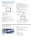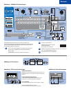
Step 1. Install the CM6800 and all components of your
system.
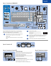
Refer to the Quick Start illustrations for an overview of system connections.
Step 2. Power-up the system.
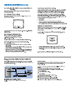
Video from camera 1 and the Time/Date Stamp appears on all system monitors.
The time stamp advances in one-second increments. WAIT FIVE SECONDS.
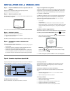
Step 3. Initialize keyboards.
From each keyboard select a monitor:
1. Enter the number of the monitor you are viewing.
2. Press the MON key.
If the keyboard LED does not display the monitor number, repeat 1 and 2.
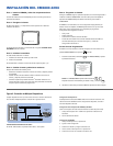
Step 4. Switch cameras and select monitors.
After initializing keyboards you can
• Select Monitors: Enter the monitor number, and then press the MON key.
• Switch Cameras: Press PREV or NEXT, or enter the camera number and
then press the CAM key.
• Control Extended Coaxitron
®
Protocol Receivers: Select a suitable camera
and operate a PTZ function. Other receiver control protocols require
programming changes.
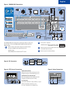
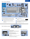
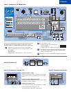
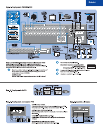
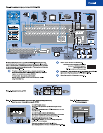
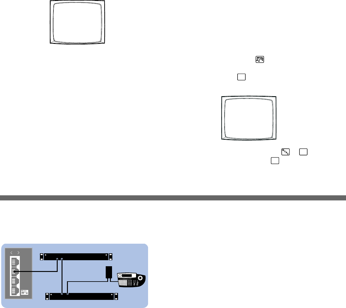
Figure 2. Connecting Multiple M Devices
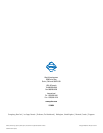
0001 E CAM 1
0001 01-JAN-01 01:01:01
Any single M device can be connected to Port 3 using a straight cable. If multiple
devices are needed, connect as illustrated below.
CM6800-32X6 INSTALLATION
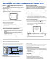
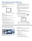
Step 5. Program your system.
Configure the CM6800 to your specific application in programming mode or
through the CM6800-MGR software. Refer to the CM6800-MGR Quick Start
Guide for instructions on installing the CM6800-MGR.
The CM6800 is shipped from the factory with default programming settings. If the
defaults are acceptable, the CM6800 can be operated without any user
programming. However, you may want to program the following settings:
• Time and date
• Camera titles
• PTZ control via hard-wire data connections
• Communication ports – To connect remote keyboards to COM 4 (the
alternate connection shown in Figure 1), change the Port 4 settings.
Access programming mode:
If you have not already done so, select the monitor. If the Camera menu appears
on the KBD960/KBR960 LCD display, press
to exit.
1. Press the PGM key (or select
PGM
on the KBD960/KBR960). The Password
screen appears.
NOTE: On the KBD960/KBR960 you must first select and
DEF
. Then
enter the Define PIN (Default: 1234), and select
MENU
.
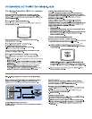
2. Enter the default password: 2899100. The Main Menu appears.
PELCO VIDEO SWITCHER
MODEL CM6800
PASSWORD TO MAIN MENU
**********
SCRATCHPAD SEQUENCE
MACRO STATUS VIEW
RETURN
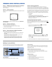
Device Settings:
Each M device connected to the CM6800 must have a unique local address. For
detailed instructions on device settings, refer to the appropriate device manual.
ALM2064 and REL2064 DIP Switch Settings:
(Note: DIP switches are located behind the front panel cover.)
1. Set SW2, DIP switches 1-8 to the appropriate local address positions.
2. Cycle power.
KBD960 Settings:
1. Set DIP switch 2 to the ON position.
2. Enter Setup Mode.
3. Select the baud rate and set the local address.
4. Return DIP switch 2 to the OFF position.
5. Press the EXIT icon on the keyboard LCD screen.
010101
1
2
3
4
KBD960
USE KBD960
COM 1
REL2064
ALM2064
RS-485
OUT IN
OUT IN
COM 3 DEFAULTS:
M, RS-485, 19200 baud, no parity, 8 data bits, 1 stop bit