2 Pelco Manual C632M (2/88)
2.0 SCOPE
The information contained within this manual covers
the installation and operation of the EA2000 Half-duplex
Equalizing Amplifier.
3.0 DESCRIPTION
The EA2000 is a prioritized, half-duplex equalizing
amplifier intended for, but not restricted to, use with
Pelco’s Coaxitron
®
System 2000 control.
In the absence of a Coaxitron control signal, the ampli-
fier functions identically to an ordinary unidirectional
equalizer, providing up tp 8 dB of flat gain and high
frequency boost of up to 18 dB at 12 MHz.
In the presence of a control signal, the “forward” equal-
izing function is temporarily suspended while the con-
trol signal is regenerated, pre-equalized and transmitted
in the “reverse” direction.
Note that the control direction has priority over the video
direction, but that this “interruption” occupies less than
one TV line period (excluding sync pulses) and that
precautions are taken to insure that the synthetically
generated video signal during this interruption does not
contain deleterious anomolies.
The EA2000 provides a low cost, highly effective means
of maintaining CCTV picture quality in runs of up to
3,000 feet (914 m) of RG59 cable.
Through panel controls provide for adjustable ampli-
fier flat gain of 1-8 dB plus adjustable high frequency
boost of from 0 to greater than 18 dB at 12 MHz.
Applications of the EA2000 should be for post-
equalization only (located near the Coaxitron trans-
mitter); use as a pre-equalizer is not allowed.
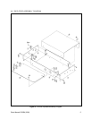
This desk top unit can be rack mounted using the R300
Rack Mount Kit.
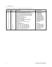
3.1 OPTIONS
R300 Rack mount kit (up to 3 units can be
racked horizontally)
4.0 INSTALLATION
The EA2000 is designed to be used for post equaliza-
tion only (located near the Coaxitron transmitter); use
as a pre-equalizer is not allowed.
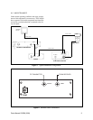
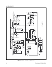
Figure 1 illustrates a typical system installation.
For installation, perform the following steps:
1. Connect the video cable from the Coaxitron re-
ceiver to the connector marked “INPUT” on the
rear panel.
2. Connect a video cable from the connector marked
“OUTPUT” to the Coaxitron transmitter (see Fig-
ure 2).
The EA2000 is supplied with a U.L. listed wall trans-
former which plugs into a 120 VAC outlet and supplies
the 12 VAC to operate the unit.
5.0 OPERATION
Optimum performance is achieved if an oscilloscope
and a standard EIA resolution chart are used in making
gain and boost adjustments. The GAIN control should
be adjusted for an output level to 1 volt p-p and the L.F.
BOOST control should be adjusted for minimum tilt
during sync pulses. The H.F. BOOST control is then
adjusted for optimum resolution wedge reproduction.
If the use of a resolution chart is precluded, the H.F.
BOOST control should be adjusted for maximum sharp-
ness of sync pulse edges — without overshoot.
In the absence of an oscilloscope, a less precise (but often
equally satisfactory) adjustment can be made as follows:
1. Set the GAIN and BOOST controls approximately
1/3 turn from fully counterclockwise.
2. Adjust GAIN control for satisfactory overall pic-
ture contrast.
3. Adjust L.F. BOOST control for optimum detail.
Too much boost (clockwise) can cause picture in-
stability and/or smearing (trail).
4. Adjust the H.F. BOOST control to further optimize
picture detail. Note that the effectiveness of this
control is hardly perceptible unless very fine pic-
ture detail is present in the camera signal output.
An excessive setting of this control (clockwise) can,
however, increase picture noise.