


2 Pelco Manual C630M Rev A (8/90)
3.1 OPTIONS
DT200 Dual desktop mount kit; two units
can be mounted side-by-side in one
desktop chassis.
R300 Rack mounting kit. Up to three (3)
units may be racked horizontally In a
single rack kit. Blank filler panels
provided for use when less than three
units are racked.
4.0 OPERATION
Optimum performance Is achieved if an oscilloscope a
standard EIA resolution chart are used in making gain
and boost adjustments. The (GAIN control should be
adjusted for an output level of 1 volt p-p and the L.F.
BOOST control should be adjusted for minimum tilt
during sync pulses. The H.F. BOOST control is then
adjusted for optimum resolution wedge reproduction.
If the use of a resolution chart is precluded, the H.F.
BOOST control should be adjusted for maximum sharp-
ness of sync pulse edges—without overshoot.
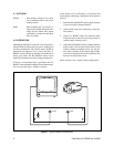
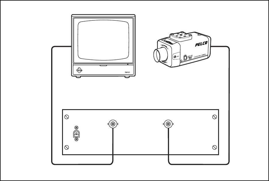
Figure 1. Typical System Configuration
In the absence of an oscilloscope, a less precise (but
often equally satisfactory) adjustment can be made as
follows:
1. Set the GAIN and BOOST controls approximately
1/3 turn from fully counterclockwise.
2. Adjust GAIN control for satisfactory overall pic-
ture contrast.
3. Adjust L.F. BOOST control for optimum detail.
Too much boost (clockwise) can cause picture in-
stability and/or smearing (trail).
4. Adjust the H.F. BOOST control to further optimize
picture detail. Note that the effectiveness of this
control is hardly perceptible unless very fine pic-
ture detail is present in the camera signal output.
An excessive setting of this control (clockwise) can,
however, increase picture noise.
Refer to Figure 1 for a typical system configuration.
OUTPUT INPUT
12 VAC