


2
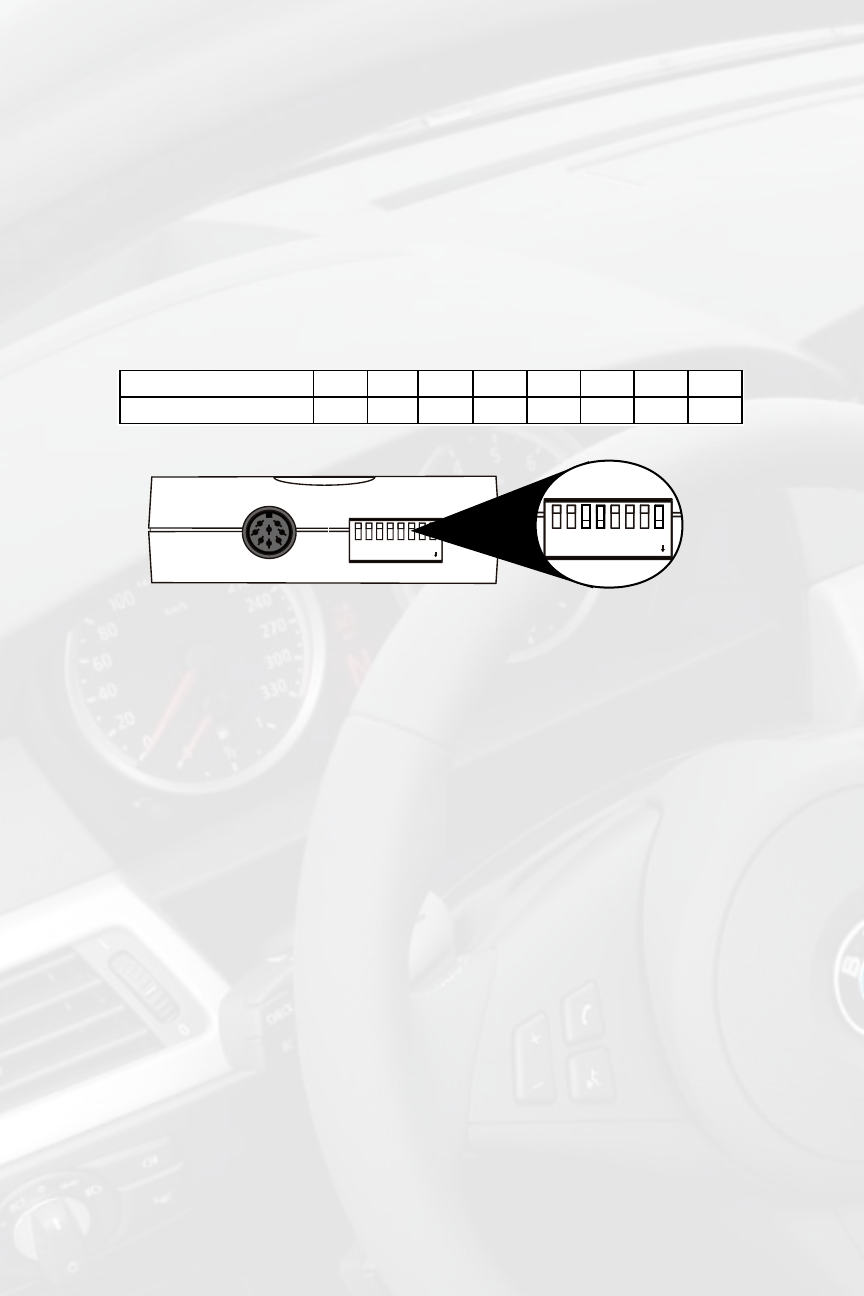
Dip Switch Conguration Chart
Fig. 1 Side view of interface with dip switches in correct position
MAKE 1 2 3 4 5 6 7 8
BMW / MINI COOPER off off ON ON
off off off
ON
TOP VIEW
1 2
3
4
5
6
7
8
DIP
ON
DIN CONNECTOR / DIP SWITCH VIEW
22-PIN HARNESS VIEW
OFF
ON
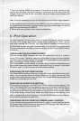
5. Installation
1. When making electrical connections it is always recommended that the vehi-
cle’s battery be disconnected from the electrical system before performing the
installation.(see precautions in section 2)
2. Locate the Factory CD changer (reference the owners manual of your vehicle
for this specic location.) If your vehicle is equipped with a factory CD changer,
it must be disconnected in order to connect the iSimple BMW interface. If your
vehicle is not equipped with a Factory CD changer you will need to locate the fac-
tory pre-run harness. This may involve the removal of the center console, glove
box, or carpeted side panels in the trunk.
3. Program the ISBM72 interface by setting the Dip switches to the conguration
for your vehicle (see section 4). Connect the vehicle adaptor harness into the fac-
tory pre-run CD changer cable(3-pin and 6-pin connectors.) Connect the 24-pin
connector of the vehicle harness into the ISBM72.
4. Connect the iPod docking cable into the 8-pin port on the side of the ISBM72.
5. Before permanently routing the iPod docking cable through the vehicle to the
desired mounting location, power on the factory radio and check for proper opera-
tion of the ISBM72.
6. The ISBM72 is designed to operate like a factory CD changer from your radio
controls. Press the button that would access the factory CD changer, to select the
iPod interface.
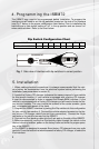
4. Programming the ISBM72
The ISBM72 may need to be programmed before installation. To program the
interface you will need to set the dip switches located on the side of the interface
(see Fig. 1 below) to the proper conguration listed below. Prior to installation the
switches are in their default setting of “off” in the up position and are turned “on”
when switched down. Refer to the chart below.
TOP VIEW
1 2
3
4
5
6
7
8
DIP
ON
DIN CONNECTOR / DIP SWITCH VIEW
22-PIN HARNESS VIEW