


Pin
No.
Signal Assignment
Pin
No.
Signal Assignment
Pin
No.
Signal Assignment
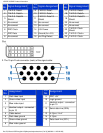
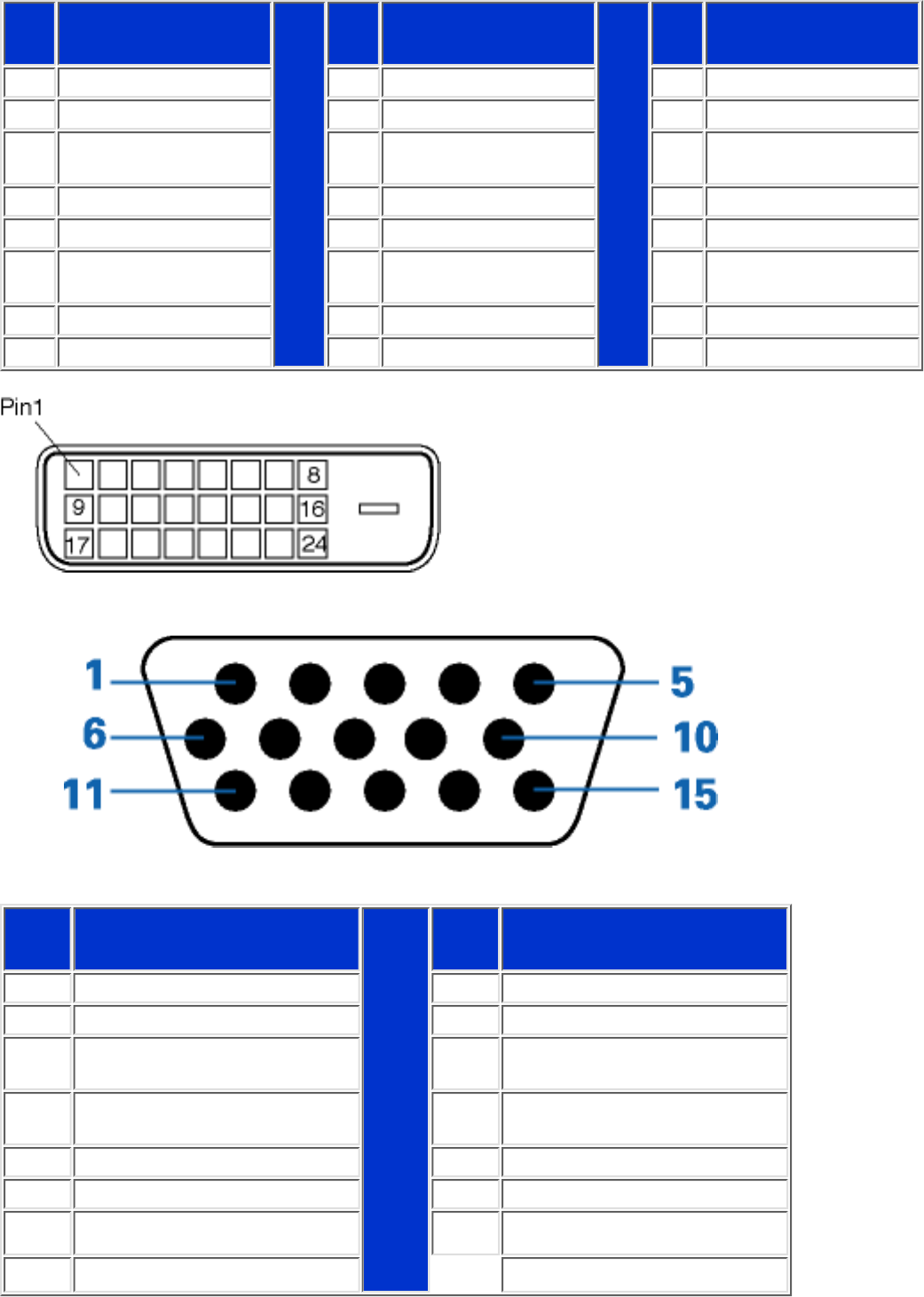
1 T.M.D.S. Data2- 9 T.M.D.S. Data1- 17 T.M.D.S. Data0-
2 T.M.D.S. Data2+ 10 T.M.D.S. Data1+ 18 T.M.D.S. Data0+
3
T.M.D.S. Data2/4
Shield
11
T.M.D.S. Data1/3
Shield
19
T.M.D.S. Data0/5
Shield
4 No connect 12 No connect 20 No connect
5 No connect 13 No connect 21 No connect
6 DDC Clock 14 +5V Power 22
T.M.D.S. Clock
Shield
7 DDC Data 15 Ground (for +5V) 23 T.M.D.S. Clock+
8 No connect 16 Hot Plug Detect 24 T.M.D.S. Clock-
2. The 15-pin D-sub connector (male) of the signal cable:
Pin
No.
Assignment
Pin
No.
Assignment
1 Red video input 9 DDC +5V
2 Green video input 10 Logic ground
3 Blue video input 11
Identical output - connected
to pin 10
4
Identical output - connected
to pin 10
12 Serial data line (SDA)
5 Cable detect 13 H. Sync / H+V
6 Red video ground 14 V. Sync
7 Green video ground 15 Data clock line (SCL)
8 Blue video ground
150P2E/150P2D Product Information
file:///D|/Grace/150P2/english/150p2e/product/product.htm (5 of 8) [8/9/2001 11:25:22 AM]