


Installation FRANÇAISInstallation ENGLISH
Note:
• Check all connections and systems before final
installation.
• Do not use unauthorized parts. The use of
unauthorized parts may cause malfunctions.
• Consult with your dealer if installation requires
drilling of holes or other modifications of the
vehicle.
• Do not install this unit where:
— it may interfere with operation of the vehicle.
— it may cause injury to a passenger as a result
of a sudden stop.
• The semiconductor laser will be damaged if it
overheats. Install this unit away from hot places
such as near the heater outlet.
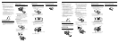
• Optimum performance is obtained when the unit
is installed at an angle of less than 60°.
DIN Front/Rear-mount
This unit can be properly installed either from
“Front” (conventional DIN Front-mount) or
“Rear” (DIN Rear-mount installation, utilizing
threaded screw holes at the sides of unit chassis).
For details, refer to the following installation
methods.
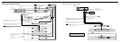
DIN Front-mount
Installation with the rubber bush
1. Insert the mounting sleeve into the dashboard.
• When installing in a shallow space, use a sup-
plied mounting sleeve. If there is enough
space behind the unit, use factory supplied
mounting sleeve.
2. Secure the mounting sleeve by using a screwdriv-
er to bend the metal tabs (90°) into place.
3. Install the unit as illustrated.
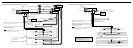
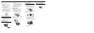
Removing the Unit
1. Extend top and bottom of the trim ring outwards
to remove the trim ring. (When reattaching the
trim ring, point the side with a groove downwards
and attach it.)
• It becomes easy to remove the trim ring if the
front panel is released.
2. Insert the supplied extraction keys into both sides
of the unit until they click into place.
3. Pull the unit out of the dashboard.
53
182
60°
Trim ring
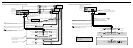
DIN Rear-mount
1. Extend top and bottom of the trim ring outwards
to remove the trim ring. (When reattaching the
trim ring, point the side with a groove downwards
and attach it.)
• It becomes easy to remove the trim ring if the
front panel is released.
2. Determine the appropriate position where the
holes on the bracket and the side of the unit
match.
3. Tighten two screws on each side.
• Use either truss screws (5 mm
× 8 mm) or
flush surface screws (5 mm × 9 mm), depend-
ing on the shape of screw holes in the
bracket.
Fastening the front panel
If you do not plan to detach the front panel, the
front panel can be fastened with supplied screw.
Screw
Trim ring
Screw
Dashboard or Console
Factory radio mounting bracket
Dashboard
Mounting sleeve
Rubber bush
Screw
Remarque:
• Vérifiez toutes les connexions et tous les
systèmes avant l’installation finale.
• N’utilisez aucune pièce non autorisée.
L’utilisation de pièces non autorisées peut causer
un mauvais fonctionnement.
• Consultez votre revendeur si l’installation
nécessite que vous perciez des trous ou effectuiez
d’autres modifications du véhicule.
• N’installez pas l’appareil dans un endroit où:
— il peut gêner la conduite du véhicule.
— il peut causer des blessures à un passager à la
suite d’un arrêt brutal.
• Le laser à semi-conducteur sera endommagé en
cas de surchauffe. Installez cet appareil à l’écart
des endroits chauds tels que près de la sortie du
chauffage.
• Des performances optimales peuvent être
obtenues quand l’appareil est installé avec un
angle de moins de 60°.
Montage avant/arrière DIN
Cet appareil peut être installé correctement par
“l’avant” (montage avant conventionnel DIN) ou
par “l’arrière” (montage par l’arrière DIN, en util-
isant les trous taraudés de chaque côté du châs-
sis). Pour les détails, reportez-vous aux méthodes
d’installation suivantes.
Montage avant DIN
Installation avec l’amortisseur en caoutchouc
1. Insérez le manchon de montage dans le tableau de
bord.
• Si l’installation se fait dans un emplacement
étroit, utilisez le manchon de montage fourni.
S’il y a suffisamment de place derrière
l’appareil, utilisez le manchon de montage
fourni avec la voiture.
2. Fixez le manchon de montage en utilisant un
tournevis pour tordre les languettes de métal
(90°).
3. Installez l’appareil comme montré sur l’illustra-
tion.
Retrait de l’appareil
1. Étendez la partie supérieure et inférieure de la
garniture vers l’extérieur pour la retirer. (Pour
fixez de nouveau la garniture, dirigez le côté avec
la fente vers le bas et fixez-la.)
• Il est plus facile de retirer la garniture quand
le panneau avant est détaché.
2. Insérez les clés d’extraction fournies de chaque
côté de l’appareil jusqu’à ce que vous entendiez
un déclic.
3. Tirez l’appareil pour le sortir du tableau de bord.
53
182
60°
Montage arrière DIN
1. Étendez la partie supérieure et inférieure de la
garniture vers l’extérieur pour la retirer. (Pour
fixez de nouveau la garniture, dirigez le côté avec
la fente vers le bas et fixez-la.)
• Il est plus facile de retirer la garniture quand
le panneau avant est détaché.
2. Déterminez la position appropriée dans laquelle
les trous du support de montage coïncident avec
ceux du côté de l’appareil.
3. Serrez deux vis de chaque côté.
• Utilisez des vis à tête bombée (5 mm ×
8 mm) ou des vis à tête encastrée (5 mm ×
9 mm), en fonction de la forme des trous dans
le support.
Fixation du panneau avant
Si vous ne prévoyez pas de détacher le panneau
avant, il peut être fixé avec la vis fournie.
Amortisseur en
caoutchouc
Vis
Manchon de montage
Tableau de bord
Garniture
Garniture
Vis
Tableau de bord ou console
Support de montage fourni avec la voiture
Vis