


Black plate (14,1)
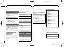
This unit
4 56
2
3
1
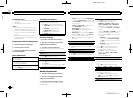
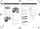
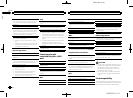
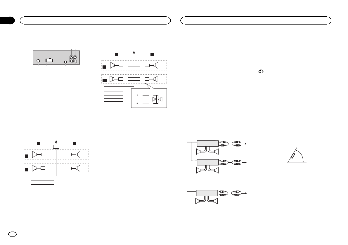
1 Power cord input
2 Rear output orsubwoofer output
3 Front output (DEH-X3600UI and DEH-X36UI
only)
4 Antenna input
5 Fuse (10 A)
6 Wired remoteinput (DEH-X3600UI and DEH-
X36UI only)
Hard-wired remote control adapter can be
connected (sold separately).
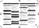
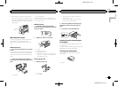
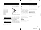
Power cord
Perform these connections when not connect-
ing a rear speaker lead to a subwoofer.
1
8
9
c
d
6
32
4
5
7
a
b
e
f
h
g
LR
F
R
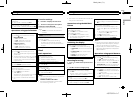
Perform these connections when using a sub-
woofer without the optional amplifier.
1
8
9
c
d
6
32
4
7
a
b
a
b
e
f
h
g
LR
F
SW
i
j
d
c
k l
1 To powercord input
2 Left
3 Right
4 Front speaker
5 Rear speaker
6 White
7 White/black
8 Gray
9 Gray/black
a Green
b Green/black
c Violet
d Violet/black
e Black (chassis ground)
Connect to a clean, paint-free metal location.
f Yellow
Connect to the constant 12 V supply termi-
nal.
g Red
Connect to terminal controlled by ignition
switch (12 V DC).
h Blue/white
Connect to system control terminal of the
power amp or auto-antenna relay control ter-
minal (max. 300 mA 12 V DC).
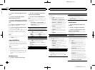
i Subwoofer (4W)
j When using a subwoofer of70 W (2W), be
sure to connect the subwoofer to the violet
and violet/black leads of this unit. Do not
connect anything to the green and green/
black leads.
k Not used.
l Subwoofer (4W)×2
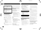
Notes
! When using a two-speaker system, do not
connect anything to speaker leads that are
not connected to a speaker.
! Change the initial menu of this unit. Refer to
SP-P/O MODE (rear output and preout set-
ting) on page 12.
The subwoofer output of this unit is monau-
ral.
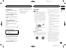
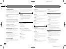
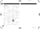
Power amp (sold separately)
Perform these connections when using the op-
tional amplifier.
DEH-X3600UI/DEH-X36UI
1
1
3
2
4
55
3
2
6
77
DEH-X2600UI/DEH-X26UI
1
3
2
6
77
1 System remote control
Connect to Blue/white cable.
2 Power amp (sold separately)
3 Connect with RCA cables (soldseparately)
4 To Front output
5 Front speaker
6 To Rearoutput or subwoofer output
7 Rear speakeror subwoofer
Installation
Important
! Check all connections and systems before
final installation.
! Do not use unauthorized parts as this may
cause malfunctions.
! Consult your dealer if installation requires
drilling of holes or other modifications to the
vehicle.
! Do not install this unit where:
— it may interfere withoperation of the vehicle.
— it may causeinjury to a passenger asa result
of a suddenstop.
! The semiconductor laser will be damaged if
it overheats. Install this unit away from hot
places such as near the heater outlet.
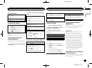
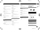
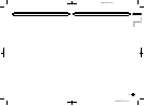
! Optimum performance is obtained when the
unit is installed at an angle of less than 60°.
60°
Installation
14
Section
Installation
En
03
<QRD3201-A>14