


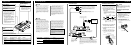
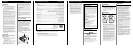

Connection Diagram
CAUTION:
To prevent damage and/or injury
• Do not ground the speaker wire directly or con-
nect a negative (–) lead wire for several speakers.
• This unit is for vehicles with a 12-volt battery and
negative grounding. Before installing it in a recre-
ational vehicle, truck or bus, check the battery
voltage.
• If the car stereo is kept on for a long time while
the engine is at rest or idling, the battery may go
dead. Turn the car stereo off when the engine is at
rest or idling.
• If the system remote control wire of the amplifier
is connected to the power terminal through the
ignition switch (12 V DC), the amplifier will
always be on when the ignition is on— regardless
of whether the car stereo is on or off. Because of
this, the battery could go dead if the engine is at
rest or idling.
• Speakers to be connected to the amplifier should
conform with the standards listed below. If they
do not conform, they may catch fire, emit smoke
or become damaged. The speaker impedance must
be 2 Ω to 8 Ω for stereo connection, and 4 Ω to
8 Ω for monaural and other bridge connection.
• Install and route the separately sold battery wire
as far away as possible from the speaker wires.
Install and route the separately sold battery wire,
ground wire, speaker wires and the amplifier as
far away as possible from the antenna, antenna
cable and tuner.
• Cords for this product and those for other prod-
ucts may be different colors even if they have the
same function. When connecting this product to
another product, refer to the supplied manuals of
both products and connect cords that have the
same function.
Connecting the Unit
ENGLISH
CAUTION
• Disconnect the negative (–) terminal of the battery
to avoid the risk of short-circuit and damage to
the unit.
• Secure the wiring with cable clamps or adhesive
tape. To protect the wiring, wrap adhesive tape
around it where they lie against metal parts.
• Do not route wires where they will get hot, for
example where the heater will blow over them. If
the insulation heats up, it may become damaged,
resulting in a short-circuit through the vehicle
body.
• Make sure that wires will not interfere with mov-
ing parts of the vehicle, such as the gearshift,
handbrake or seat sliding mechanism.
• Do not shorten any wires. Otherwise the protec-
tion circuit may fail to work when it should.
• Never feed power to other equipment by cutting
the insulation of the power supply wire to tap
from the wire. The current capacity of the wire
will be exceeded, causing overheating.
• Never replace the fuse with one of greater value
or rating than the original fuse. Use of an improp-
er fuse could result in overheating and smoke and
could cause damage to the product and injury
including burns.
Fuse (30 A)
Grommet
Special red battery wire [RD-223] (sold separately)
After making all other connections at the amplifier,
connect the battery wire terminal of the amplifier to
the positive (+) terminal of the battery.
Ground wire (black) [RD-223] (sold separately)
Connect to metal body or chassis.
Fuse (30 A) × 2
Car stereo with
RCA output jacks
External Output
Connecting wire with RCA
pin plugs (sold separately).
RCA input jack
Speaker output terminal
See the “Connecting the
Speaker Wires” section
for speaker connection
instructions.
System remote control wire (sold separately)
Connect the male terminal of this wire to the system remote control
terminal of the car stereo (SYSTEM REMOTE CONTROL). The
female terminal can be connected to the auto-antenna relay control
terminal. If the car stereo does not have a system remote control ter-
minal, connect the male terminal to the power terminal through the
ignition switch.
Speaker Channel Speaker Type Power
Two-channel
Subwoofer Nominal input: Min. 120 W
Other than subwoofer Max. input: Min. 250 W
One-channel
Subwoofer Nominal input: Min. 420 W
Other than subwoofer Max. input: Min. 760 W
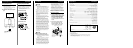
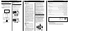
Setting the Unit
ENGLISH
Gain Control
If the sound level is too low, even
when the volume of the car stereo
used along with this power amplifier
is turned up, turn gain control on the
front of the power amplifier
clockwise. If the sound distorts when
the volume is turned up, turn the gain
control counter-clockwise.
• When using with an RCA equipped car
stereo (standard output of 500 mV), set
to the NORMAL position. When using
with an RCA equipped Pioneer car
stereo with max. output of 4 V or more,
adjust level to match the car stereo
output level.
• If you hear too much noise when using
the speaker input terminals, turn the gain
control counter-clockwise.
Bass Boost Level Control
Switch
You can select a bass boost level
from 0 dB, 6 dB and 12 dB.
Power Indicator
The power indicator lights when the
power is switched on.
Fuse (30 A)
Front side
Back side
LPF (Low-Pass Filter) Select Switch
Set the LPF select switch as follows according to the type of speaker that is connected to the
speaker output connector and the car stereo system:
LPF Select Audio frequency range Speaker Remarks
Switch to be output Type
LPF (right) 80 Hz and below with Subwoofer Connect a subwoofer.
–12 dB/oct. cut off slope
OFF (left) Full range Full range
Speaker input terminal
See the “Using the
Speaker Input” section.
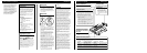
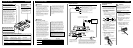
Connecting the Power Terminal
• Always use the special red battery and ground
wire [RD-223], which is sold separately. Connect
the battery wire directly to the car battery positive
terminal (+) and the ground wire to the car body.
1. Pass the battery wire from the
engine compartment to the interior
of the vehicle.
• After making all other connections to the
amplifier, connect the battery wire terminal of
the amplifier to the positive (+) terminal of
the battery.
2. Twist the battery wire, ground wire
and system remote control wire.
3. Attach lugs to wire ends. Lugs not
supplied.
• Use pliers, etc., to crimp lugs to wires.
4. Connect the wires to the terminal.
• Fix the wires securely with the terminal
screws.
WARNING
Failure to securely fasten the battery wire to the ter-
minal using the terminal screws could cause the ter-
minal area to overheat and could result in damage
and injury including minor burns.
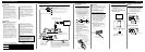
Connecting the Speaker Output
Terminals
1. Expose the end of the speaker wires
using nippers or a cutter by about
10 mm (3/8 inch) and twist.
2. Attach lugs to speaker wire ends.
Lugs not supplied.
• Use pliers, etc., to crimp lugs to wires.
3. Connect the speaker wires to the
speaker output terminals.
• Fix the speaker wires securely with the termi-
nal screws.
Fuse (30 A)
Engine
compart-
ment
Interior of
the vehicle
Drill a 14 mm
(1/2 inch) hole
into the vehicle
body.
Insert the O-ring rubber
grommet into the vehicle
body.
Positive terminal
GND terminal
Power terminal
Battery wire
System remote
control terminal
System remote
control wire
Ground wire
Speaker
output
terminal
Terminal screw
Fuse (30 A)
Speaker wire
BFC (Beat Frequency
Control) Switch
If you hear a beat while
listening to an AM broadcast
with your car stereo, change
the BFC switch using a small
standard tip screwdriver.