


Connecting the Unit ENGLISH
Setting the Gain properly
• This unit is equipped with a protective function to
prevent malfunction of the unit itself and speakers
from too much output, improper use or improper
connection.
• When outputting sound at high volume etc., this
function will cut off the sound output in a few
seconds. But this is not a malfunction. When you
turn down the volume of the head unit the sound
output will be restored.
• If sound output is cut, the gain control of this unit
may be improperly set. To ensure continuous
sound output at increased volume of the head unit,
set the gain control of the amplifier to a proper
position according to the preout maximum output
level of the head unit.
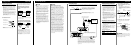
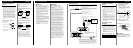
Gain Control of This Unit
• The above illustration shows the gain set to
NORMAL.
There is no need to decrease the volume of the
head unit and too much output is controlled.
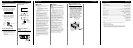
Relationship between the gain of the
amplifier and the output power of the
head unit
• If you raise the gain of the amplifier to an improp-
er level, only distortion is increased and the power
increases only slightly.
Signal waveform when outputting at high
volume by the gain control of the amplifier
• With high output the signal waveform is distorted,
if you raise the gain of the amplifier the power
changes only slightly.
• If you decrease the volume of the head unit and
set the gain control of the amplifier to the proper
position but still the sound cuts out from time to
time, contact the nearest authorized PIONEER
Service Station.
Equal power
Amplifier gain
(normal)
Amplifier gain
(maximum)
Signal
waveform
Signal
waveform
Normal gain
Maximum gain
Amplifier gain
(normal)
Amplifier gain
(maximum)
Head unit volume steps
Power
Normal gain
Power
Head unit volume steps
Maximum gain
Equal power
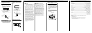
Solderless Terminal Connections
• Do not connect a cord having an exposed core
wire to the power terminals of this amplifier
(Power terminal, GND terminal, System remote
control terminal). Disconnection or breakage of
the core wire can cause a fire or short-circuit.
• Since the wire will become loose over time, it
must be periodically inspected and tightened as
necessary.
• Do not solder or bind the ends of the twisted
wires.
• Fasten while making sure to not to clamp the
insulating sheath of the wire.
• Use the supplied hexagonal wrench to tighten and
loosen the terminal screw of the amplifier.
Securely fasten the wire with the terminal screw.
However, since excessively tightening the terminal
screw of the System remote control has the risk of
damaging the wire, be careful not to tighten
excessively by observing the status of the wire
when tightening.
Connecting the Power Terminal
• We recommend that you use the special red bat-
tery and ground wire [RD-228], which is sold sep-
arately. Connect the battery wire directly to the
car battery positive terminal (+) and the ground
wire to the car body.
• Recommended wires size (AWG: American Wire
Gauge) is as follows. The battery wire and the
ground wire must be same size.
• Use a 10 AWG to 20 AWG wire for the system
remote control wire.
Battery Wire and Ground Wire Size
Wire Length less than less than less than
5.7 m 9.0 m 14.4 m
Wire Size 8 AWG6 AWG4 AWG
1. Pass the battery wire from the
engine compartment to the interior
of the vehicle.
• After making all other connections to the
amplifier, connect the battery wire terminal of
the amplifier to the positive (+) terminal of
the battery.
2. Connect the wires to the terminal.
• Fix the wires securely with the terminal
screws.
WARNING
Failure to securely fasten the battery wire to the ter-
minal using the terminal screws could cause the ter-
minal area to overheat and could result in damage
and injury including minor burns.
Engine
compartment
Interior of
the vehicle
Drill a 13 mm
hole into the
vehicle body.
Insert the O-ring rubber
grommet into the vehicle
body.
Positive (+)
terminal
Fuse (40 A) × 2
GND terminal
Power terminal
Battery wire
System remote
control terminal
System remote
control wire
Ground wire
Terminal screws
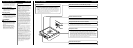
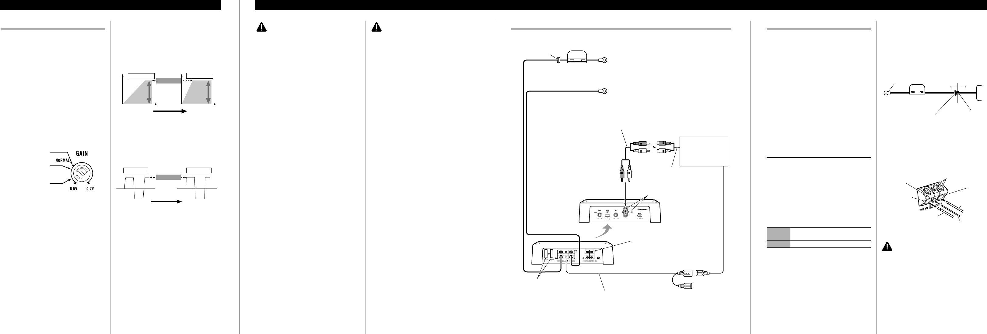
Connection Diagram
• This diagram shows connections using external output (subwoofer output). Slide the input switch to the right
(RCA).
Fuse (40 A) × 2
Grommet
Special red battery wire [RD-228] (sold separately)
After making all other connections at the amplifier,
connect the battery wire terminal of the amplifier to
the positive (+) terminal of the battery.
Ground wire (black) [RD-228] (sold separately)
Connect to metal body or chassis.
Fuse (25 A) × 2
Car stereo with
RCA output jacks
External Output
(Subwoofer output)
Connecting wire with RCA
pin plugs (sold separately).
RCA input jack
Speaker terminal
See the “Connecting the Speaker Wires”
section for speaker connection instructions.
System remote control wire (sold separately)
Connect the male terminal of this wire to the system remote control
terminal of the car stereo (SYSTEM REMOTE CONTROL). The
female terminal can be connected to the auto-antenna relay control
terminal. If the car stereo does not have a system remote control ter-
minal, connect the male terminal to the power terminal through the
ignition switch.
Reverse side
CAUTION
• Disconnect the negative (–) terminal of the battery
to avoid the risk of short-circuit and damage to
the unit.
• Secure the wiring with cable clamps or adhesive
tape. To protect the wiring, wrap adhesive tape
around it where they lie against metal parts.
• Do not route wires where they will get hot, for
example where the heater will blow over them. If
the insulation heats up, it may become damaged,
resulting in a short-circuit through the vehicle
body.
• Make sure that wires will not interfere with mov-
ing parts of the vehicle, such as the gearshift,
handbrake or seat sliding mechanism.
• Do not shorten any wires. Otherwise the protec-
tion circuit may fail to work when it should.
• Never feed power to other equipment by cutting
the insulation of the power supply wire to tap
from the wire. The current capacity of the wire
will be exceeded, causing overheating.
• Never replace the fuse with one of greater value
or rating than the original fuse. Use of an improp-
er fuse could result in overheating and smoke and
could cause damage to the product and injury
including burns.
CAUTION:
To prevent damage and/or injury
• Do not ground the speaker wire directly or con-
nect a negative (–) lead wire for several speakers.
• This unit is for vehicles with a 12-volt battery and
negative grounding. Before installing it in a recre-
ational vehicle, truck or bus, check the battery
voltage.
• If the car stereo is kept on for a long time while
the engine is at rest or idling, the battery may go
dead. Turn the car stereo off when the engine is at
rest or idling.
• If the system remote control wire of the amplifier
is connected to the power terminal through the
ignition switch (12 V DC), the amplifier will
always be on when the ignition is on— regardless
of whether the car stereo is on or off. Because of
this, the battery could go dead if the engine is at
rest or idling.
• DO NOT connect a subwoofer with a lower
impedance than specified in the “Connecting the
Speaker Wires” section. Amplifier damage,
smoke, and overheating could result from a non-
specified connection. The amplifier surface could
also become hot to the touch and minor burns
could result.
• Connect either of two subwoofers to the amplifier;
1: a subwoofer with a 250 W or larger nominal
input and an impedance 4 Ω, or 2: a subwoofer
with a 420 W or larger nominal input and an
impedance 2 Ω. If the nominal input and imped-
ance are out of the above ranges, the subwoofer
may catch fire, emit smoke or become damaged.
• Install and route the separately sold battery wire
as far away as possible from the speaker wires.
Install and route the separately sold battery wire,
ground wire, speaker wires and the amplifier as
far away as possible from the antenna, antenna
cable and tuner.
Preout level: 2 V
(Standard: 500 mV)
Preout level: 4 V
Preout level: 6.5 V
Setting the Unit ENGLISH