


Specifications
Installation
GM-X362
Power source.............................................................................................................. 14.4 V DC (10.8 — 15.1 V allowable)
Grounding system ............................................................................................................................................ Negative type
Current consumption ........................................................................................................ 11.3 A (at continuous power, 4 Ω)
Average current drawn* ............................................................................................................ 3.8 A (4 Ω for two channels)
5.9 A (4 Ω for one channel)
Fuse .................................................................................................................................................................................. 20 A
Dimensions ........................................................................................................................ 279 (W) × 61 (H) × 157 (D) mm
[11 (W) × 2-3/8 (H) × 6-1/8 (D) in]
Weight ........................................................................................................ 2.6 kg (5.7 lbs) (Leads for wiring not included)
Maximum power output ...................................................................................................................... 80 W × 2 / 200 W × 1
Continuous power output .......................................................... 40 W × 2 (at 14.4 V, 4 Ω, 20 — 20,000 Hz, 0.08% THD)
100 W × 1 (at 14.4 V, 4 Ω, 20 — 20,000 Hz, 0.8% THD)
50 W × 2 (at 14.4 V, 2 Ω, 20 — 20,000 Hz, 0.8% THD)
Load impedance ............................................................................................................................ 4 Ω (2 — 8 Ω allowable)
(Bridge connection: 4 — 8 Ω allowable)
Frequency response ............................................................................................................ 10 — 50,000 Hz (+0 dB, –1 dB)
Signal-to-noise ratio ...................................................................................................................... 100 dB (IHF–A network)
Distortion ............................................................................................................................................ 0.008% (10 W, 1 kHz)
Separation ........................................................................................................................................................ 60 dB (1 kHz)
Low pass filter ................................................................................................................................ Cut off frequency: 80 Hz
Cut off slope: –12 dB/oct
Maximum input level/impedance .................................................................................... RCA: 6.5 V/22 kΩ (0.4 — 6.5 V)
Speaker: 26 V/40 kΩ (1.6 — 26 V)
Note:
• Specifications and the design are subject to possible modification without notice
due to improvements.
*Average current drawn
• The average current drawn is nearly the maximum current drawn by this unit
when an audio signal is input. Use this value when working out total current
drawn by multiple power amplifiers.
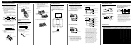
CAUTION
• Do not install in:
—Places where it could injure the driver or pas-
sengers if the vehicle stops suddenly.
—Places where it may interfere with the driver,
such as on the floor in front of the driver’s
seat.
• Make sure that wires are not caught in the sliding
mechanism of the seats, resulting in a short-cir-
cuit.
• Confirm that no parts are behind the panel when
drilling a hole for installation of the amplifier.
Protect all cables and important equipment such
as fuel lines, brake lines and electrical wiring
from damage.
• Install tapping screws in such a way that the
screw tip does not touch any wire. This is impor-
tant to prevent wires from being cut by vibration
of the car, which can result in fire.
• To prevent electric shock, do not install the ampli-
fier in places where it might come in contact with
liquids.
• To ensure proper installation, use the supplied
parts in the manner specified. If any parts other
than the supplied ones are used, they may damage
internal parts of the amplifier, or they may
become loose causing the amplifier to shut down.
To prevent malfunction
• To ensure proper heat dissipation of the amplifier,
be sure of the following during installation.
—Allow adequate space above the amplifier for
proper ventilation.
—Do not cover the amplifier with a floor mat or
carpet.
• Do not install the amplifier near a door where it
may get wet.
• Do not install the amplifier on unstable places
such as the spare tire board.
• The best location for installation differs with the
car model and installation location. Secure the
amplifier at a sufficiently rigid location.
• Make temporary connections first and check that
the amplifier and the system operate properly.
• After installing the amplifier, confirm that the
spare tire, jack and tools can be easily removed.
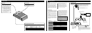
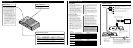
Example of installation on the floor
mat or on the chassis
1. Place the amplifier where it is to be
installed. Insert the supplied tapping
screws (4 × 18 mm) into the screw
holes. Push on the screws with a
screwdriver so they make marks
where the installation holes are to be
located.
2. Drill 2.5 mm (1/8 inch) diameter
holes at the point marked, and
install the amplifier, either on the
carpet or directly to the chassis.
Drill a 2.5 mm (1/8 inch)
diameter hole
Tapping-screws
(4 × 18 mm)
Floor mat
or chassis
GM-X262
Power source.............................................................................................................. 14.4 V DC (10.8 — 15.1 V allowable)
Grounding system ............................................................................................................................................ Negative type
Current consumption ........................................................................................................ 11.3 A (at continuous power, 4 Ω)
Average current drawn* ............................................................................................................ 3.8 A (4 Ω for two channels)
5.9 A (4 Ω for one channel)
Fuse .................................................................................................................................................................................. 20 A
Dimensions ........................................................................................................................ 279 (W) × 61 (H) × 157 (D) mm
[11 (W) × 2-3/8 (H) × 6-1/8 (D) in]
Weight ........................................................................................................ 2.6 kg (5.7 lbs) (Leads for wiring not included)
Maximum power output ...................................................................................................................... 80 W × 2 / 200 W × 1
Continuous power output .......................................................... 40 W × 2 (at 14.4 V, 4 Ω, 20 — 20,000 Hz, 0.08% THD)
100 W × 1 (at 14.4 V, 4 Ω, 20 — 20,000 Hz, 0.8% THD)
50 W × 2 (at 14.4 V, 2 Ω, 20 — 20,000 Hz, 0.8% THD)
Load impedance ............................................................................................................................ 4 Ω (2 — 8 Ω allowable)
(Bridge connection: 4 — 8 Ω allowable)
Frequency response ............................................................................................................ 10 — 50,000 Hz (+0 dB, –1 dB)
Signal-to-noise ratio ...................................................................................................................... 100 dB (IHF–A network)
Distortion ............................................................................................................................................ 0.008% (10 W, 1 kHz)
Separation ........................................................................................................................................................ 60 dB (1 kHz)
Low pass filter ................................................................................................................................ Cut off frequency: 80 Hz
Cut off slope: –12 dB/oct
Maximum input level/impedance .................................................................................... RCA: 6.5 V/22 kΩ (0.4 — 6.5 V)
Speaker: 26 V/40 kΩ (1.6 — 26 V)
Note:
• Specifications and the design are subject to possible modification without notice
due to improvements.
*Average current drawn
• The average current drawn is nearly the maximum current drawn by this unit
when an audio signal is input. Use this value when working out total current
drawn by multiple power amplifiers.