


3
5
6
7
8
F
E
D
C
B
A
5
6
7
8
GM-X372/XH/UC
1. SPECIFICATIONS
CONTENTS
SAFETY INFORMATION ............................................2
1. SPECIFICATIONS........................................................3
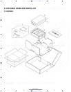
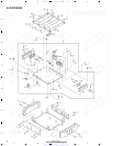
2. EXPLODED VIEWS AND PARTS LIST.......................4
2.1 PACKING...............................................................4
2.2 EXTERIOR.............................................................6
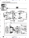
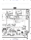
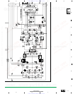
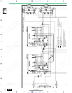
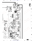
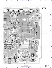
3. SCHEMATIC DIAGRAM .............................................8
3.1 OVERALL CONNECTION DIAGRAM(GUIDE PAGE)....8
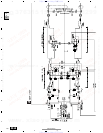
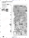
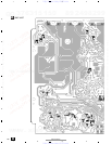
4. PCB CONNECTION DIAGRAM ................................14
4.1 AMP UNIT...........................................................14
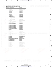
5. ELECTRICAL PARTS LIST ........................................18
6. ADJUSTMENT..........................................................19
7. GENERAL INFORMATION .......................................20
7.1 DIAGNOSIS ........................................................20
7.1.1 DISASSEMBLY .........................................20
7.1.2 CONNECTOR FUNCTION DESCRIPTION.......21
7.2 IC ........................................................................22
8. OPERATIONS............................................................23
Power source.............................................................................................................. 14.4 V DC (10.8 — 15.1 V allowable)
Grounding system ............................................................................................................................................ Negative type
Current consumption
........................................................................................................ 14.4 A (at continuous power, 4 Ω)
Average current drawn*
............................................................................................................ 5.0 A (4 Ω for two channels)
7.5 A (4 Ω for one channel)
Fuse
............................................................................................................................................................................ 25 A × 1
Dimensions
......................................................................................................................... 255 (W) × 50 (H) × 169 (D) mm
[10 (W) × 2 (H) × 6-5/8 (D) in]
Weight
......................................................................................................... 2.0 kg (4.4 lbs) (Leads for wiring not included)
Maximum power output
.................................................................................................................... 100 W × 2 / 240 W × 1
Continuous power output
..................... ...................................... 50 W × 2 (at 14.4 V, 4 Ω, 20 — 20,000 Hz, 0.15% THD)
120 W × 1 (at 14.4 V, 4 Ω, 20 — 20,000 Hz, 0.8% THD)
60 W × 2 (at 14.4 V, 2 Ω, 20 — 20,000 Hz, 0.8% THD)
Load impedance ............................................................................................................................ 4 Ω (2 — 8 Ω allowable)
(Bridge connection: 4 — 8 Ω allowable)
Frequency response ............................................................................................................ 10 — 50,000 Hz (+0 dB, –1 dB)
Signal-to-noise ratio
..................... .................................................................................................. 100 dB (IHF–A network)
Distortion
.............................................................................................................................................. 0.008% (10 W, 1 kHz)
Separation
......................................................................................................................................................... 60 dB (1 kHz)
Low pass filter ................................................................................................................................ Cut off frequency: 80 Hz
Cut off slope: –12 dB/oct
Maximum input level/impedance .................................................................................... RCA: 6.5 V/22 kΩ (0.2 — 6.5 V)
Speaker: 26 V/40 kΩ (0.8 — 26 V)
Note:
• Specifications and the design are subject to possible modification without notice
due to improvements.
*Average current drawn
• The average current drawn is nearly the maximum current drawn by this unit
when an audio signal is input. Use this value when working out total current
drawn by multiple power amplifiers.
Backup current ................................................................................................................................................. 3.0 mA or less
http://www.xiaoyu163.com
http://www.xiaoyu163.com