


Connecting the UnitsConnecting the UnitsConnecting the UnitsConnecting the Units
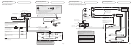
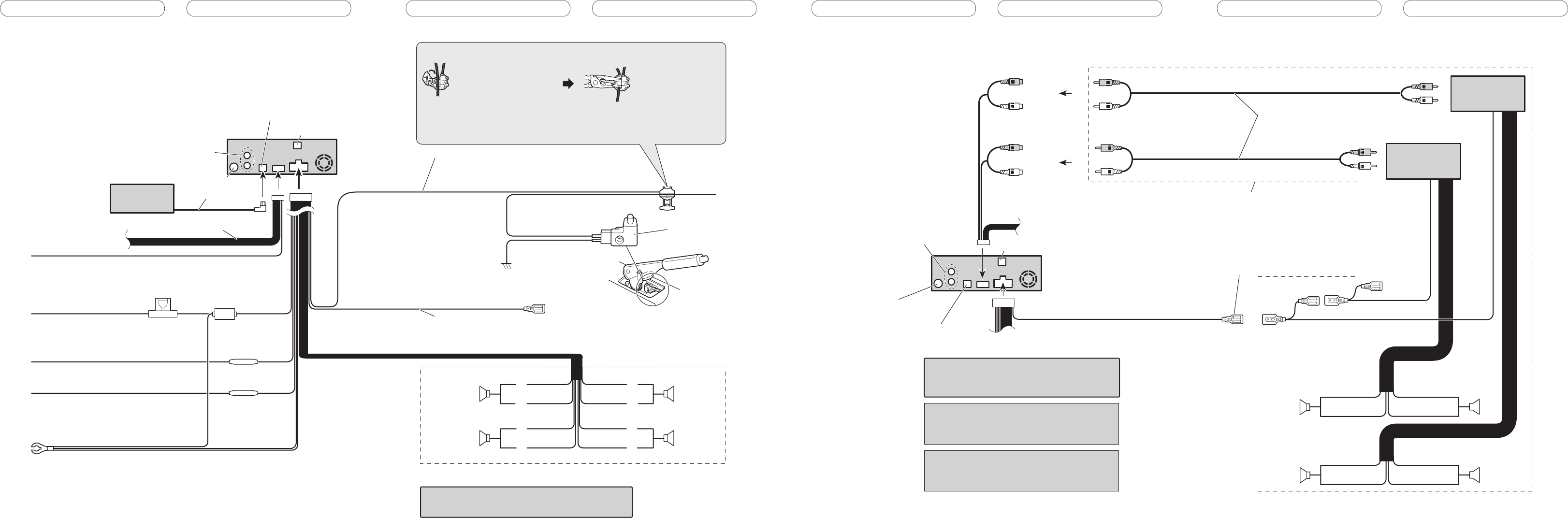
Power cable connection
Use this for connections when
you have the separately available
amplifier.
Blue/white
To system control terminal of the
power amp or Auto-antenna relay
control terminal
(max. 300 mA 12 V DC).
System remote control
Subwoofer
Subwoofer
Front speaker
Front speaker
Connecting cords
with RCA pin plugs
(sold separately)
Subwoofer output
or non fading output
(SUBWOOFER OUTPUT or
NON-FADING OUTPUT)
Front output
(FRONT OUTPUT)
Left Right
System remote control
15 cm (5-7/8 in.)
15 cm (5-7/8 in.)
Note
Change the initial setting of this product (refer to the
Operation Manual). The subwoofer output of this unit
is monaural.
This product
≠
+
≠
+
≠
+
≠
+
Power amp
(sold separately)
Optical input
Power amp
(sold separately)
Antenna jack
(Refer to Fig. 2.)
IP-BUS input (Blue)
(Refer to Fig. 2.)
When you connect separately sold multi-channel
processor (DEQ-P7000) to this unit, do not connect
anything to the speaker leads and system remote
control (blue/white).
Note
When you connect DEQ-P7000 to this unit, separately
sold power amp must be connected to DEQ-P7000.
Rear audio output
(Refer to Fig. 4 and Fig. 6.)
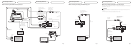
Connecting to separately sold power amp
Fuse holder
Fuse resistor
Fuse resistor
Blue/white
To system control terminal of the power amp
or Auto-antenna relay control terminal
(max. 300 mA 12 V DC).
Yellow
To terminal always supplied
with power regardless of
ignition switch position.
Red
To electric terminal controlled
by ignition switch (12 V DC)
ON/OFF.
Black (ground)
To vehicle (metal) body.
Orange/white
To lighting switch terminal.
White
White/black
Gray
Gray/black
Green
Green/black
Violet
Violet/black
Front speaker
Rear speaker
Front speaker
Rear speaker
Left Right
With a 2 speaker system, do not connect anything
to the speaker leads that are not connected to speakers.
Yellow/black
If you use a cellular telephone, connect it via the
Audio Mute lead on the cellular telephone. If not,
keep the Audio Mute lead free of any
connections.
IP-BUS cable
+
≠
+
≠
+
≠
+
≠
Light green
Used to detect the ON/OFF status of the parking brake.
This lead must be connected to the power supply side of the
parking brake switch.
Parking brake
switch
Power supply side
Ground side
Note
• The position of the parking brake switch depends
on the vehicle model. For details, consult the
vehicle Owner’s Manual or dealer.
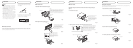
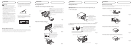
Connection method
Clamp the lead.1. 2. Clamp firmly with
needle-nosed
pliers.
This product
Antenna jack
IP-BUS input (Blue)
Optical input
When you connect separately sold multi-channel processor
(DEQ-P7000) to this unit, do not connect anything to the
speaker leads and system remote control (blue/white).
Refer to Fig.3–Fig.6.
Multi-CD player
(sold separately)
Rear audio output
(Refer to Fig. 4 and Fig. 6.)
Fig. 2 Fig. 3