


7
Connecting the Unit
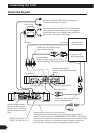
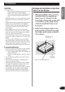
Connection Diagram
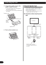
Grommet
RCA input
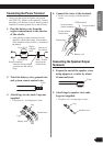
Special red battery wire [RD-223] (sold separately)
After making all other connections at the amplifier,
connect the battery wire terminal of the amplifier to
the positive (+) terminal of the battery.
Ground wire (Black) [RD-223] (sold separately)
Connect to metal body or chassis.
Amplifier with
RCA input jacks
Car stereo with
RCA output jacks
System remote control wire (sold separately)
Connect the male terminal of this wire to the system remote control
terminal of the car stereo (SYSTEM REMOTE CONTROL). The female
terminal can be connected to the auto-antenna relay control terminal. If the
car stereo does not have a system remote control terminal, connect the
male terminal to the power terminal through the ignition switch.
Fuse (30 A)
Fuse (30 A)
Connecting wires with RCA pin
plugs (sold separately).
Connecting wires with RCA pin
plugs (sold separately).
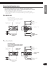
Speaker output terminal
See the “Connecting the
Speaker wires” section for
speaker connection instruc-
tions.
GM-X574: Fuse (25 A) × 2
GM-X374: Fuse (30 A) × 1
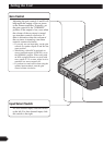
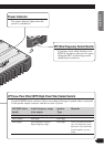
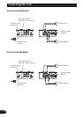
External Output
If only one input plug is used, do not
connect anything to RCA input jack B.
RCA input jack BRCA output jack
Front side
RCA input jack A
Back side
Speaker input terminal
See the “Using the Speaker Input”
section.