


CAUTION:
To prevent damage and/or injury
• Do not ground the speaker wire directly or con-
nect a negative (–) lead wire for several speakers.
• This unit is for vehicles with a 12-volt battery and
negative grounding. Before installing it in a recre-
ational vehicle, truck or bus, check the battery
voltage.
• If the car stereo is kept on for a long time while
the engine is at rest or idling, the battery may go
dead. Turn the car stereo off when the engine is at
rest or idling.
• If the system remote control wire of the amplifier
is connected to the power terminal through the
ignition switch (12 V DC), the amplifier will
always be on when the ignition is on— regardless
of whether the car stereo is on or off. Because of
this, the battery could go dead if the engine is at
rest or idling.
• DO NOT connect a subwoofer with a lower
impedance than specified in the “Connecting the
Unit” section. Amplifier damage, smoke, and
overheating could result from a non-specified con-
nection. The amplifier surface could also become
hot to the touch and minor burns could result.
• Connect either of two subwoofers to the amplifier;
1: a subwoofer with a 500 W or larger nominal
input and an impedance 4 Ω, or 2: a subwoofer
with a 1,000 W or larger nominal input and an
impedance 2 Ω. If the nominal input and imped-
ance are out of the above ranges, the subwoofer
may catch fire, emit smoke or become damaged.
• Install and route the separately sold battery wire
as far away as possible from the speaker wires.
Install and route the separately sold battery wire,
ground wire, speaker wires and the amplifier as
far away as possible from the antenna, antenna
cable and tuner.
• Cords for this product and those for other prod-
ucts may be different colors even if they have the
same function. When connecting this product to
another product, refer to the supplied Installation
manuals of both products and connect cords that
have the same function.
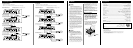
Connecting the Unit
CAUTION
• Disconnect the negative (–) terminal of the battery
to avoid the risk of short-circuit and damage to
the unit.
• Secure the wiring with cable clamps or adhesive
tape. To protect the wiring, wrap adhesive tape
around it where they lie against metal parts.
• Do not route wires where they will get hot, for
example where the heater will blow over them. If
the insulation heats up, it may become damaged,
resulting in a short-circuit through the vehicle
body.
• Make sure that wires will not interfere with mov-
ing parts of the vehicle, such as the gearshift,
handbrake or seat sliding mechanism.
• Never feed power to other equipment by cutting
the insulation of the power supply wire to tap
from the wire. The current capacity of the wire
will be exceeded, causing overheating.
• Never replace the fuse with one of greater value
or rating than the original fuse. Use of an improp-
er fuse could result in overheating and smoke and
could cause damage to the product and injury
including burns.
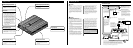
Setting the Unit
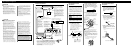
Connection Diagram
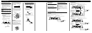
Bass Boost Frequency Control
You can select a bass boost frequency
from 40 to 120 Hz with the bass boost
control.
Power Indicator
The power indicator lights when the
power is switched on.
Bass Boost Level Control
Bass boost level control can boost the
level around the frequency selected by
the bass boost frequency control from 0
to 12 dB.
Cut Off Frequency Control for LPF
You can select a cut off frequency from
40 to 240 Hz.
Gain Control
If the sound level is too low, even when
the volume of the car stereo used along
with this power amplifier is turned up,
turn gain control on the front of the
power amplifier clockwise. If the sound
distorts when the volume is turned up,
turn the gain control counter-clockwise.
• When using with an RCA equipped car
stereo (standard output of 500 mV), set
to the NORMAL position. When using
with an RCA equipped Pioneer car
stereo with max. output of 4 V or
more, adjust level to match the car
stereo output level.
• For synced amplifier’s gain control,
see the “Setting the Gain for Synced
Amplifier” section.
Subsonic Select Switch
The subsonic filter cuts inaudible fre-
quencies below 20 Hz to eliminate
unwanted vibrations and minimize
power loss.
MODE SELECT Switch
You can select amplifier’s sync mode
from MASTER, SYNC and SYNC INV.
For the position of the MODE SELECT
switch, see the “Connecting the Speaker
Wires” section.
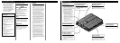
Grommet
Battery wire (sold separately)
For the wire size, see the
“Connecting the Power Terminal”
section. The battery wire, the ground
wire and the optional direct ground
wire must be same size.
After making all other connections
at the amplifier, connect the battery
wire terminal of the amplifier to the
positive (+) terminal of the battery.
Ground wire (sold separately)
The ground wires must be same size
as the battery wire.
Connect to metal body or chassis.
Car stereo with
RCA output
jacks
External Output
(Subwoofer output)
Connecting wire with RCA
pin plugs (sold separately).
RCA input jack
Speaker terminal
See the “Connecting the
Speaker Wires” section for
speaker connection instruc-
tions.
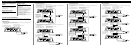
System remote control wire (sold separately)
Connect the male terminal of this wire to the system remote control termi-
nal of the car stereo (SYSTEM REMOTE CONTROL). The female termi-
nal can be connected to the auto-antenna relay control terminal. If the car
stereo does not have a system remote control terminal, connect the male ter-
minal to the power terminal through the ignition switch.
Grommet
Reverse side
The maximum length
of the wire between the
fuse and the positive
(+) terminal of the bat-
tery is 45 cm (18 in.).
Positive (+)
terminal
Negative (–)
terminal
Battery
Optional direct ground
wire (sold separately)
When chassis ground-
ing is not sufficient,
direct grounding
should be used. The
wire size should be
same size as the bat-
tery wire.
Fuse (100 A)
Each amplifier must be SEPARATELY
fused at 100 A.
SYNC OUTPUT /
SYNC INPUT jack
See the “Connecting the
Speaker Wires” section
for SYNC OUTPUT /
SYNC INPUT jack con-
nection instructions.
Grommet