


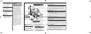
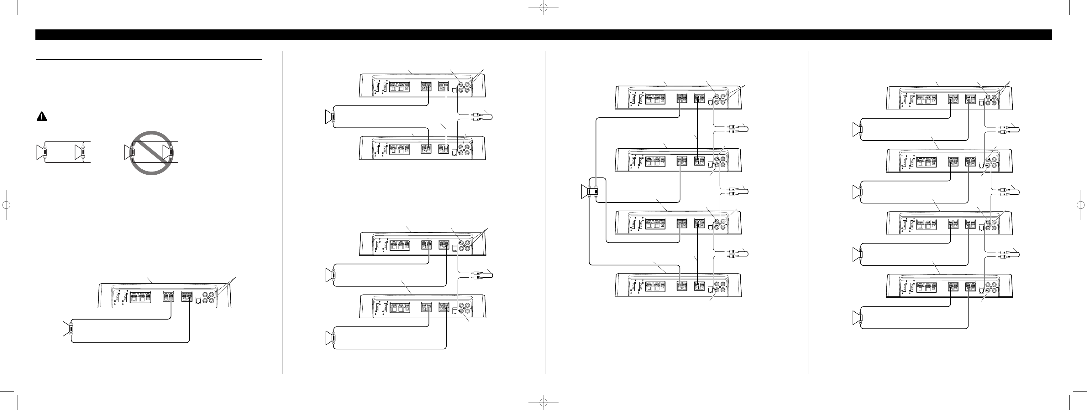
Connecting the Unit <ENGLISH>
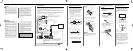
Connecting the Speaker Wires
Connect the speaker leads and set MODE SELECT switch and POWER MODE switch to suit the configuration
according to the figures shown below and the next page.
•When synchronously connecting two or more amplifiers in combination, only use these amplifiers. Do not
mix these amplifiers with other amplifiers.
•When synchronously connecting two or more amplifiers in combination, set the gain control, subsonic select
switch, cut off frequency control for LPF and bass boost control on the amplifier that has been set to MAS-
TER with the MODE SELECT switch. These settings are inactive when set on an amplifier set to SYNC or
SYNC INV.
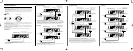
CAUTION
Do NOT install or use this amplifier by wiring speakers rated at 2 Ω (or lower) in parallel to achieve a 1 Ω (or
lower) bridged mode (Diagram B).
Amplifier damage, smoke, and overheating could result from improper bridging. The amplifier surface could
also become hot to the touch and minor burns could result.
To properly install or use a bridged mode and achieve a 2 Ω load, wire two 4 Ω speakers in parallel with Left +
and Right – (Diagram A) or use a single 2 Ω speaker.
If the synthetic impedance is from 2 Ω to less than 4 Ω,always make sure to set the POWER MODE switch to
the HI-CURRENT position.
In addition, refer to the speaker instruction manual for information on the correct connection procedure.
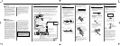
Single Amplifier
• Use speakers having an impedance from 1 Ω to 8 Ω.
•The setting of the POWER MODE switch varies according to the speaker impedance. See the “Setting the
Unit” section for details.
Diagram A - Proper
2 Ω Bridged Mode
4 Ω
Speaker
4 Ω
Speaker
Diagram B - Improper
1 Ω Bridged Mode
2 Ω
Speake
r
2 Ω
Speaker
MODE SELECT switch must
be in MASTER position.
Connect to a car stereo.
For details, see the “Connection Diagram”.
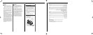
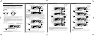
Two Amplifier (Ex. Bridge)
• Only use speakers having an impedance of 2 Ω to 16 Ω. In addition, in the case of connecting multiple
speakers with a bridge, check that the synthetic impedance is at least 2 Ω.
•The setting of the POWER MODE switch varies according to the speaker impedance. Slide the POWER
MODE switch to the HI-CURRENT position if the impedance is from 2 Ω to less than 4 Ω, or slide it to the
NORMAL position if the impedance is from 4 Ω to 16 Ω. The same setting is used for both amplifiers.
•When switching to the SYNC INV mode, the seal over the MODE SELECT switch must be peeled off and
you can find SYNC INV switch. Peel off the seal after checking that connections are correct.
Two Amplifier
• Use speakers having an impedance from 1 Ω to 8 Ω.
•The setting of the POWER MODE switch varies according to the speaker impedance. See the “Setting the
Unit” section for details. The same setting is used for both amplifiers.
MODE SELECT
switch must be in
SYNC INV position.
Connecting wire with RCA
pin plugs (sold separately).
Connecting
speaker wire
(sold separately).
MODE SELECT switch
must be in SYNC position.
1 Ω to 8 Ω
MODE SELECT switch must
be in MASTER position.
Connect to a car stereo.
For details, see the
“Connection Diagram”.
2 Ω to 16 Ω
1 Ω to 8 Ω
1 Ω to 8 Ω
SYNC OUTPUT
MODE SELECT switch must
be in MASTER position.
Connect to a car stereo.
For details, see the
“Connection Diagram”.
Connecting wire with RCA
pin plugs (sold separately).
SYNC INPUT
SYNC OUTPUT
SYNC INPUT
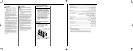
Four Amplifier (Ex. Bridge)
MODE SELECT switch
must be in MASTER position.
Connecting wire with RCA
pin plugs (sold separately).
MODE SELECT switch must
be in SYNC INV position.
Connect to a car stereo.
For details, see the
“Connection Diagram”.
MODE SELECT switch must be
in SYNC INV position.
MODE SELECT switch must
be in SYNC INV position.
Connecting wire with RCA
pin plugs (sold separately).
Connecting wire with RCA
pin plugs (sold separately).
Connecting speaker
wire (sold separately).
Connecting speaker
wire (sold separately).
SYNC OUTPUT
SYNC INPUT
SYNC OUTPUT
SYNC INPUT
2 Ω to
16 Ω
• Only use speakers having an impedance of 2 Ω to 16 Ω. In addition, in the case of connecting multiple
speakers with a bridge, check that the synthetic impedance is at least 2 Ω.
•The setting of the POWER MODE switch varies according to the speaker impedance. Slide the POWER
MODE switch to the HI-CURRENT position if the impedance is from 2 Ω to less than 4 Ω, or slide it to the
NORMAL position if the impedance is from 4 Ω to 16 Ω. The same setting is used for four amplifiers.
•When switching to the SYNC INV mode, the seal over the MODE SELECT switch must be peeled off and
you can find SYNC INV switch. Peel off the seal after checking that connections are correct.
Four Amplifier
MODE SELECT switch
must be in MASTER position.
MODE SELECT switch
must be in SYNC position.
MODE SELECT switch
must be in SYNC position.
MODE SELECT switch
must be in SYNC position.
1 Ω to 8 Ω
1 Ω to 8 Ω
1 Ω to 8 Ω
1 Ω to 8 Ω
SYNC OUTPUT
SYNC
INPUT
SYNC
OUTPUT
SYNC INPUT
• Use speakers having an impedance from 1 Ω to 8 Ω.
•The setting of the POWER MODE switch varies according to the speaker impedance. See the “Setting the
Unit” section for details. The same setting is used for four amplifiers.
Connect to a car stereo.
For details, see the
“Connection Diagram”.
Connecting wire with RCA
pin plugs (sold separately).
Connecting wire with RCA
pin plugs (sold separately).
Connecting wire with RCA
pin plugs (sold separately).
SYNC OUTPUT
SYNC INPUT
SYNC OUTPUT
SYNC INPUT
CRD4121A_Eng 3/29/06 7:39 PM Page 9