


7
Optional Mounting Alternatives
Warning:
T
he monitor stand base may forcefully extend and cause injury. Raise the monitor to its "Full Up"
position before removing the monitor stand.
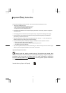
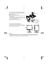
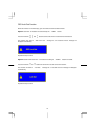
Detaching LCD Monitor from Its Stand
Unscrew screws the swivel base support column and pull
down the hinge to release.
Cable management ring.
Figure 1-6
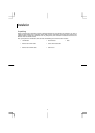
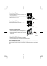
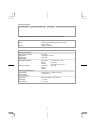
Interface for Arm Applications
Before installing to mounting device, please refer to Fig.1-3.
The rear of this LCD display has four integrated 4 mm, 0.7 pitches
threaded nuts, as well as four 5 mm access holes in the plastic
covering as illustrated in Figure 1-7. These specifications meet the
VESA Flat Panel Monitor Physical Mounting Interface Standard
(paragraphs 2.1 and 2.1.3, version 1, dated 13 November 1997).
Note :Please use M 4mm x 100m (L) screws for this
application.
Figure 1-7