


P O L K A U D I O / M O M O D E S I G N
12
A M E R I C A N P O W E R , I T A L I A N F I N E S S E
13
MM400 Component Tweeter Hook-up
When purchased as a separate unit, the MM400 tweeter includes a crossover network
integrated into the hook-up wires. This high-pass filter allows the MM400 to be used with
other components. It is important to maintain correct polarity. The red wire connects to
the positive (+) amplifier terminal and the black to the negative (-) amplifier terminal.
If your system contains an active crossover, you may bypass the in-line crossover and wire
the tweeter directly to the output terminals of an amplifier that has a high-pass filter
(crossover) on its input. The minimum crossover point should be 2 kHz at 12dB per octave.
DO NOT USE THE T WEETER W ITHOUT A C ROSSOVER N ETWORK.
Damage to the tweeter from thermal overload will result without the protection provided
by a crossover and will void your warranty.
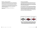
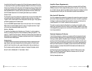
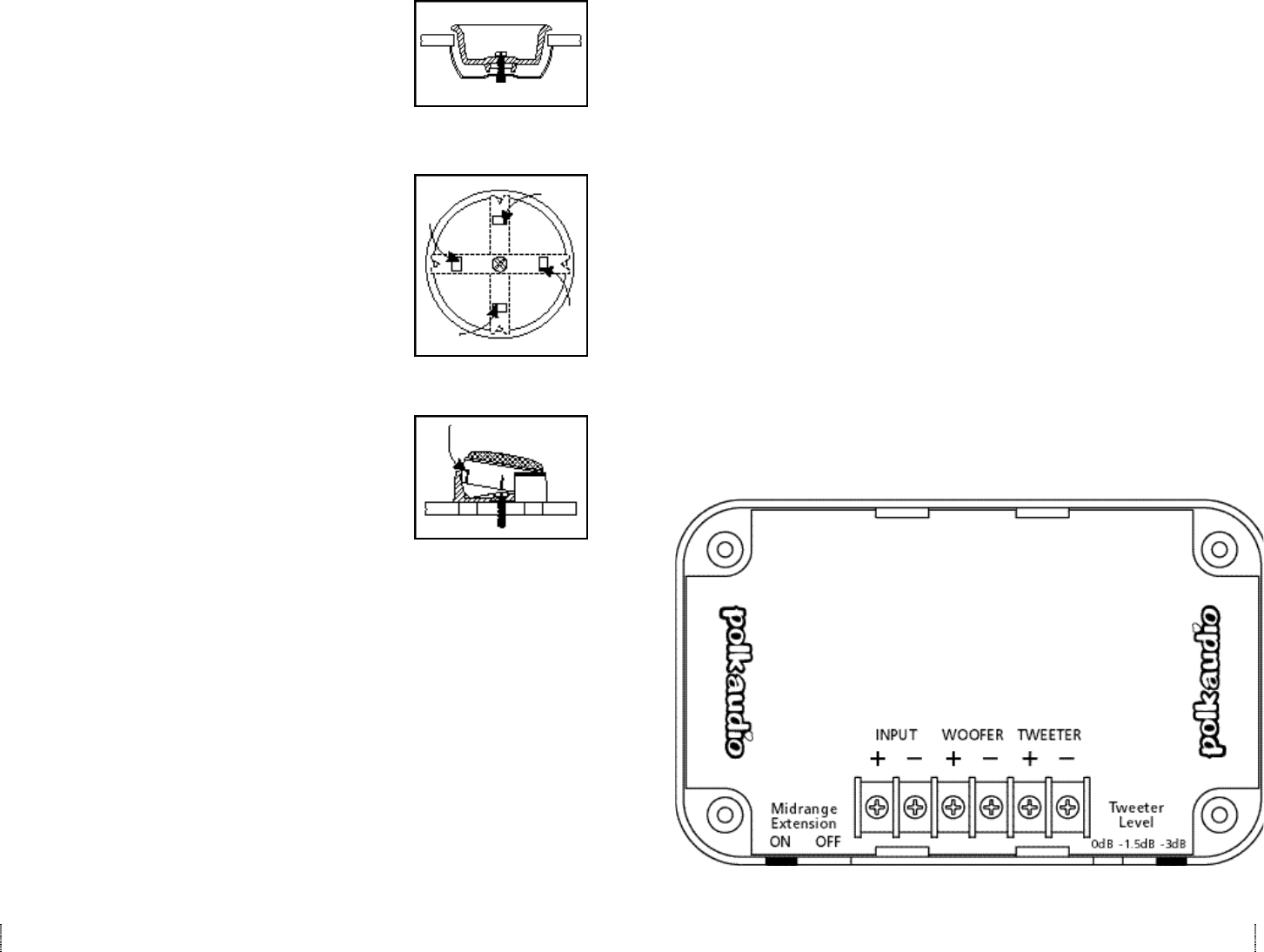
Extending Frequency Response using Mid-Range Extension
The Polk Audio/MOMO Crossover features a Mid-Range Extension option. When placed in
the “ON” position, this removes the low pass crossover filter from the mid/bass driver, allow-
ing it to run full-range. This may be helpful in getting a better “blend” between mid/driver
and tweeter when the two are placed some distance from each other.
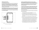
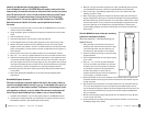
Mounting Option #2 - Flush mounting the
MM400 Tweeter
1. Remove the panel on which you are going to mount the
tweeter and check for proper clearance behind it. The
flush mount kit is 13/16 inch deep. Measure to make
sure there is sufficient depth behind the spot you
choose the final location.
2. Use the hole that is punched into the cardboard packing
insert as a template to mark the location and size of the
mounting hole.
3. Mark the center of the spot and cut a hole with the 2-
inch hole-saw attachment for your power drill. Go slow.
Or you can use a razor knife instead of a drill.
4 . Cut the supplied tweeter wire (the lighter gauge wire) in
h a l f .
5 . Strip 1/8” – 1/4” (4-6 mm) of plastic insulation from the
cut ends of the tweeter wire. Connect this end of the
wire to the tweeter terminals of the crossover. Connect
the white-striped wire strand to the positive (+) terminal
of the crossover tweeter output and the un-striped wire to
the negative (-) tweeter terminal.
6 . Route the tweeter wire from the crossover location to the
tweeter location.
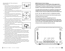
7. Assemble cup, clamp, and machine screw loosely.
8. Route the red and black tweeter wires through the holes
in the bottom of the cup.
9 . Slip the male fast-on connector on the red tweeter wire
onto the female connector on the white-striped wire from the crossover and the
black tweeter wire to the un-striped wire (Figure 2). Make sure the clear plastic
insulators fully cover the fast-on connectors otherwise you may short the tweeter
leads and possibly damage your amplifier.
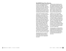
1 0 . Press the assembly into the 2” hole until the clamp edge is below the mounting
surface, then tighten the screw. The cup will clamp down to the surface as the
screw is tightened (Figure 3). In the case of a thick mounting surface, the legs of
the clamp can be bent outward by inserting a screwdriver through the four rec-
tangular holes in the cup while still mounted (Figure 4)
11. Snap the tweeter into the mounting cup, being careful not to pinch the wires.
12. Once the tweeter is mounted and connected, swivel the tweeter by applying firm
pressure to the edge of the tweeter module. DO NOT apply pressure to the grille.
NOTE: to remove the tweeter assembly, place a small screwdriver
into the side slot and pry carefully upwards (Figure 5)
Figure 3
Figure 4
Figure 5