


Part 2
II. MODEL NUMBERS
LM-2110: 10.4” LCD Monitor w/ stand
LM-2010: 10.4” LCD Monitor w/ support bracket for Posiflex hybrid
terminals HT series
III. CARTON CONTENTS
1. LCD Monitor panel unit
2. Base stand (for LM-2110) or support bracket (for LM-2010)
3. Fixing screws (2x for LM-2010, 6x for LM-2110)
4. User’s Manual
5. VGA cable: 21867244100 (for LM-2110) or 21863241730 (for LM-
2010)
6. Power adaptor: ASP0P042WTB001 & power cord (for LM-2110)
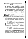
IV. INSTALLATION
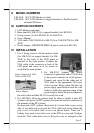
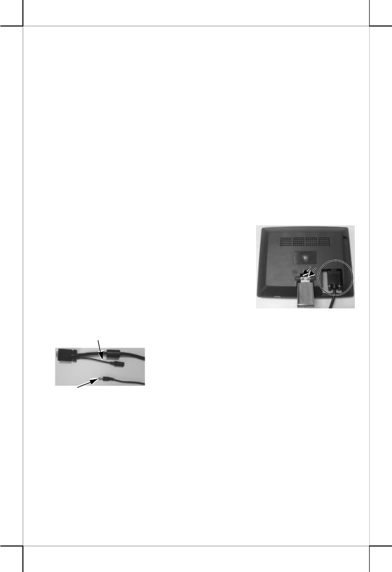
1. Use 2 fixing screws to fit the monitor stand
(for LM-2110) or support bracket (for LM-
2010) to the back of the LCD panel as
arrowed in the right picture. Connect the
VGA cable to the connector at back of the
LCD panel and screw in its fix screws as
circled in the same picture.
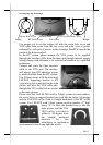
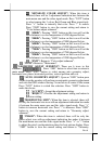
2. For LM-2110, connect the power
connector at panel back end of VGA cable
to the power connector as in left picture.
Connect and screw-fix the other end of
VGA cable to the appropriate VGA port
of host system. Please check that the city
power supply specification from the wall
socket is within the operation range of the
power adaptor. Insert the power adaptor to
the wall socket and the LM-2110 is ready for work.
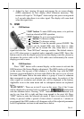
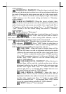
3. For LM-2010, following actions shall be taken to install it onto HT
systems with power for HT systems disconnected and also reference of
the manuals of the HT systems.
On base unit of HT systems, there must be 4 screw hole covers on top
side of its plastic top cover and the VGA cable hole cover within the
pole cover of its back cable cover as in picture below. There are 2
bridges from each screw hole cover to the HT top cover and 3 bridges
from the VGA cable hole cover to the pole cover as enlarged in the
Power Connector from
Power Adaptor
Power Connector in VGA
Cable for LM-2110