


13
12
1110
SYSTEM CONNECTIONS AND CONFIGURATION
RS232
PHONE (PAGE IN)
DOORBELL / STATUS IN
1
2
CONTROL
PORT
FIRMWARE
UPGRADE
OFF ON
COMMON
IR OUT
LO
HI
STATUS OUT:
0 to +12V
120V 60Hz 1.8A ~
FUSE: T5AL 250V
DATA I/O
CONTACT CLOSURE
EXPANSION PORTS
COMMON
M4
SOURCE 1
LOOP
OUT
IR
LOOP
L R
INPUTS
SOURCE 2
LOOP
OUT
IR
LOOP
L R
INPUTS
SOURCE 3
LOOP
OUT
IR
LOOP
L R
INPUTS
SOURCE 4
LOOP
OUT
IR
LOOP
L R
INPUTS
SOURCE 5
LOOP
OUT
IR
LOOP
L R
INPUTS
SOURCE 6
LOOP
OUT
IR
LOOP
L R
INPUTS
SPKRS
L
R
+
+ –
–
ZONE 4
L R
PRE-OUT
VC
NVC
KEYPAD
IR OUT
Riverside, CA. USA
Made in Taiwan
SPKRS
L
R
+
+ –
–
ZONE 3
L R
PRE-OUT
VC
NVC
KEYPAD
IR OUT
SPKRS
L
R
+
+ –
–
ZONE 2
L R
PRE-OUT
VC
NVC
KEYPAD
IR OUT
SPKRS
L
R
+
+ –
–
ZONE 1
L R
PRE-OUT
VC
NVC
KEYPAD
IR OUT
To
Zone 1
Keypad Jack
CAT5 Cable Carries
RS485 Control, IR Signal
and Keypad Power
From Doorbell Trigger
To Source 1
Inputs
L / R
IR Out from Source 1
IR Out from Source 2
IR Out from Source 3
IR Out from Source 4
TUNER 2
TUNER 1
SATELLITE
CD PLAYER
Speaker Feeds to Each Zone
To Source 2
Inputs
L R
To Source 3
Inputs
L R
To Source 4
Inputs
L R
IR Out from Source 5
CD PLAYER 2
To Source 5
Inputs
L R
IR Out from Source 6
MP3 PLAYER
To Source 6
Inputs
L R
IR Flasher
Zone 1
PMKIR
Keypad
SAT CD
MUTE
TNR1
TNR2
PWR
CD2
MP3
BASS
TREB
MUTE
PWR
SAT CD
TNR1
TNR2
CD2
MP3
BASS
TREB
SAT CD
MUTE
TNR1
TNR2
PWR
CD2
MP3
BASS
TREB
To
Zone 2
Keypad Jack
Zone 2
PMKIR
Keypad
SAT CD
MUTE
TNR1
TNR2
PWR
CD2
MP3
BASS
TREB
MUTE
PWR
SAT CD
TNR1
TNR2
CD2
MP3
BASS
TREB
SAT CD
MUTE
TNR1
TNR2
PWR
CD2
MP3
BASS
TREB
To
Zone 3
Keypad Jack
Zone 3
PMKIR
Keypad
SAT CD
MUTE
TNR1
TNR2
PWR
CD2
MP3
BASS
TREB
MUTE
PWR
SAT CD
TNR1
TNR2
CD2
MP3
BASS
TREB
SAT CD
MUTE
TNR1
TNR2
PWR
CD2
MP3
BASS
TREB
To
Zone 4
Keypad Jack
Zone 4
PMKIR
Keypad
SAT CD
MUTE
TNR1
TNR2
PWR
CD2
MP3
BASS
TREB
MUTE
PWR
SAT CD
TNR1
TNR2
CD2
MP3
BASS
TREB
SAT CD
MUTE
TNR1
TNR2
PWR
CD2
MP3
BASS
TREB
Factory Default System
As mentioned earlier, the M4 comes with a set of four
pre-configured PMKIR keypads, one for each zone. In
addition, the M4 is pre-programmed at the factory
with a default project so that the entire system will
function “right out of the box.” The installer can use
this default as a base on which to build customized
projects. The default project has the following
functionality: (Refer to Figures 3 & 7).
1. Six Source keys: TNR1, TNR2, SAT, CD, CD2, MP3
2. Six Function keys: BASS, TREB, MUTE, PWR, VOL UP,
VOL DOWN
3. The six Source keys are set as Zone ON keys and
are programmed to select the M4 rear panel Audio
Source inputs as follows:
TNR1 = Audio Source 1, TNR2 = Audio Source 2,
SAT = Audio Source 3, CD = Audio Source 4, CD2 =
Audio Source 5, MP3 = Audio Source 6. In addition,
a Mute Off command is programmed under each
Source key.
4. The six Function keys are programmed as follows:
BASS: 1st press changes Vol UP/Down to Bass Up/
Down. 2nd press = Bass Flat.
TREB: 1st press changes Vol Up/Down to Treble Up/
Down. 2nd press = Treble Flat.
: Volume Up command. Also serves as Bass or
Treble Up after first pressing BASS or TREB keys.
: Volume Down command. Also serves as Bass
or Treble Down after first pressing BASS or TREB keys.
NOTE:
While in the Treble or Bass tone modes, the
selected Source button will blink at a medium rate,
to indicate the tone setting mode. The tone setting
mode is defeated by one press of any button other
than the Tone and Volume buttons.
MUTE: Set for Internal Preamp Muting. Toggles
ON/OFF. Pressing Source and Volume buttons also
un-mutes. During Mute, selected source key blinks
slowly.
PWR: Set as Zone Power OFF. Will NOT turn the zone
ON. Press and Hold for two seconds turns all zones
OFF (Whole House).
Whole House/Party Mode
5. All zones are set for Whole House/Party Mode
capability Whole House/Party Mode: Forces all zones
to the same source and allows volume and mute
functions to operate all zones in unison.
- To engage Whole House/Party Mode, press and
hold a desired Source button for longer than two
seconds. During press and hold, source button
blinks rapidly (busy).
- Release button when blinking stops. Source
button then turns Amber in color, indicating
system is now in Whole House/Party Mode.
- Source selection, Volume Control and Mute
functions will now operate in all zones from the
initiating zone only.
- To transfer Whole House/Party Mode control to
another zone, above steps are repeated from the
desired zone.
- To cancel Whole House/Party Mode, press and
hold a Source button from the initiating zone for
longer than two seconds (until blinking stops).
A TYPICAL M4 INSTALLATION
Perhaps the best way to become familiar with the
M4/keypad system is to show its application in a
typical installation. Figure 7 shows the four PMKIR
keypads (included) controlling the M4 and related
source components in a four-zone application
NOTE:
The system in Figure 7 is given to illustrate
the basics on how to configure and program
a system, not to show all aspects of such an
installation. For instance, for simplicity, the speakers
in each zone are not shown in Figure 7, even though
such components would be required for a complete
working system.
NOTE:
Maximum recommended lead length for the
keypads with CAT5 cable is 1000' (305m).
The recommended steps to install such a system
would be as follows:
1. Pull all wiring for the keypads, speakers, etc., from
the various zone rooms (home runs) to a central
equipment area.
2. Set up and make all the necessary audio
connections from the source components to the
M4, the amplifiers to speakers in rooms, etc.
3. Make sure all system components function first,
with their own remote controls, before configuring
the keypads.
4. Flasher placement: Locate each source
component’s IR Sensor window. Place emitters on
each of the source components and plug them into
the corresponding Source IR Outputs on the M4.
NOTE:
Zones other than the initiating zone will have
red active Source buttons and will operate as normal
independent zones.
6. Priority is set to ON for all zones. This means
that commands from any keypad in any zone will
execute, regardless of previous command executions
in other zones.
7. When a zone is first turned on, the volume will be
at a default medium background level. After that, it
will come on at the last volume used prior to zone
turn OFF.
9
8
76
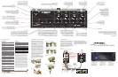
KEYPAD GANG CONFIGURATIONS
The M4 System comes with four single gang PMKIR
pre-configured keypads, one for each zone as shown
for the single gang version in Figure 3. The cover
plates and the other configurations are optional.
Screw-less “Snap-On” type cover plates are also
accommodated. Each keypad comes with a set of
factory installed “default buttons” plus a good variety
of additional buttons. The default buttons can be easily
changed to meet the needs of the installation.
PMKIR Master Keypad
(included with the M4)
MUTE
PWR
Rear View
0
1
2
3
4
5
6
7
8
9
A
B
C
D
E
F
SAT CD
TNR1
TNR2
CD2
MP3
BASS
TREB
PMKIR
Master Keypad
with IR Receiver
+ RELAY
– RELAY
+12V
DATA
GND
485 A
485 B
ADDRESS
KEYPAD EXPANSION
Riverside, CA. USA • Made in China
proficientaudio.com
SAT CD
MUTE
TNR1
TNR2
PWR
CD2
MP3
BASS
TREB
SAT CD
MUTE
TNR1
TNR2
PWR
CD2
MP3
BASS
TREB
1
6
8
PMKIR
(included)
PMKIR
Master Keypad
with IR Receiver
+ RELAY
– RELAY
+12V
DATA
GND
485 A
485 B
ADDRESS
KEYPAD EXPANSION
Riverside, CA. USA • Made in China
proficientaudio.com
2 3 4
4
5
7
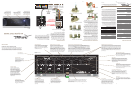
Single Gang Set-Up
1. PMKIR Source/Function Buttons – Six of this set
of eight buttons are programmed as source select
for the M4. When the system is off, all buttons have
a background green color. When a source button is
pressed, it turns to a low-level red color to show that
it is the active source and the system is on.
2. Keypad Expansion Terminal – This 16-pin header
terminal is used to inter-connect the optional numeric
and function keypad modules for expansion as
needed. A 3-connector ribbon cable is packed with
each module for making these connections.
3. Address Switch – A unique hex address must be
set for each master keypad when connected on a
common bus within a single zone. Unique addresses
are not required zone-to-zone. It provides up to 16
addresses (0 to F).
4. Snap Tabs – These tabs hold the decorator style
insert panel to the metal mounting plate and are
easily released for custom changing of the buttons.
5. Mounting Plate – Standard plate allows the
keypad module to be attached to standard in-wall
J-Boxes using the two screws provided. Allows
attachment of standard decorator type cover plates
(also screw-less snap-on plates).
6. IR Receiver Lens – Version PMKIR includes
Proficient’s exclusive ANS IR receiver, built-in. It allows
the use of a handheld remote for control of system
components.
7. Connection Terminals – for CAT5 home-run
termination. + Relay and – Relay - for future use.
+12V – Powers the keypad, including the internal IR
receiver on model PMKIR. Includes reverse voltage
protection. Data – Sends IR control signals for
control of system components. GND – Return for
power, IR signal and data. 485 A / 485 B – Balanced,
bi-directional system communications data.
8. Function Buttons
– These lower four buttons (can
be programmed for any function except source select.)
The Proficient M4 System consists of four subsystems.
First, the keypads themselves can be configured in
many key icon arrangements and placed in a one,
two or three gang set-up to meet virtually any client
requirement. They are connected via convenient
CAT5 cable with home-run lengths of up to 1000'
(305m or longer, if heavier gauge wire is used) to the
centrally located M4 Multi-Zone Audio Amplifier/
Controller located near the controlled equipment.
The M4 contains the “brains” of the system, taking
key location data from the keypads to trigger the
actual controlling IR, RS232 and RS485 commands
that are passed to all of the installed system
components. Programming is accomplished by the
use of Proficient Editor, a Proficient developed
Windows software system. A fourth item, the
optional Command Interface (sold separately), is an
installer’s tool for learning and teaching special IR
commands that are not included in the Proficient
Editor internal library.
PMKIR PNK PFK
(included) (optional) (optional)
1 2 3
4 5 6
7 8 9
0
TRK DSC
RDM
RPT
PLAY
ESC INFO
MENUGUIDE
MUTE
PWR
PMKIR PNK
MUTE
PWR
1 2 3
4 5 6
7 8 9
0
TRK DSC
RDM
PMKIR
(included)
SAT CD
MUTE
TNR1
TNR2
PWR
SEL
CD2
MP3
BASS
TREB
SAT CD
TNR1
TNR2
CD2
MP3
BASS
TREB
GBL
RPT
SAT CD
TNR1
TNR2
CD2
MP3
BASS
TREB
(included) (optional)
SAT CD
MUTE
TNR1
TNR2
PWR
CD2
MP3
BASS
TREB
SAT CD
MUTE
TNR1
TNR2
PWR
CD2
MP3
BASS
TREB
PLAY
ESC INFO
MENUGUIDE
SEL
1 2 3
4 5 6
7 8 9
0
DSC
RDM
RPT
TRK
1 2 3
4 5 6
7 8 9
0
DSC
RDM
RPT
TRK
Single Gang
Double Gang Triple Gang
MUTE
PWR
1 2 3
4 5 6
7 8 9
0
TRK DSC
RDM
SAT CD
TNR1
TNR2
CD2
MP3
BASS
TREB
GBL
RPT
SAT CD
MUTE
TNR1
TNR2
PWR
CD2
MP3
BASS
TREB
1 2 3
4 5 6
7 8 9
0
DISK
RND
RPT
TRK
PMKIR PNK
(included) (optional)
1.77"
4.07"
PNK Numeric Keypad
(Not included with M4)
1 2 3
4 5 6
7 8 9
0
TRK DSC
RDM
RPT
Rear View
9
KEYPAD EXPANSION
Riverside, CA. USA • Made in China
proficientaudio.com
PNK
Numeric Keypad
1 2 3
4 5 6
7 8 9
0
DSC
RDM
RPT
TRK
PMKIR Master Keypad
(Included with M4)
Rear View
MUTE
PWR
SAT CD
TNR1
TNR2
CD2
MP3
BASS
TREB
GBL
0
1
2
3
4
5
6
7
8
9
A
B
C
D
E
F
PMK
Master Keypad
+ RELAY
– RELAY
+12V
DATA
GND
485 A
485 B
ADDRESS
KEYPAD EXPANSION
Riverside, CA. USA • Made in China
proficientaudio.com
SAT CD
MUTE
TNR1
TNR2
PWR
CD2
MP3
BASS
TREB
2
1
3 4
6
7
4
8
5
PMKIR
Master Keypad
with IR Receiver
+ RELAY
– RELAY
+12V
DATA
GND
485 A
485 B
ADDRESS
KEYPAD EXPANSION
Riverside, CA. USA • Made in China
proficientaudio.com
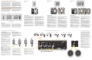
Double Gang Set-Up
1. PMKIR Source/Function Buttons – Six of this set
of eight buttons are programmed as source select
for the M4. When the system is off, all buttons have
a background green color. When a source button is
pressed, it turns to a low-level red color to show that
it is the active source and the system is on.
2. Keypad Expansion Terminal – This 16-pin header
terminal is used to inter-connect the optional numeric
and function keypad modules for expansion as
needed. A 3-connector ribbon cable is packed with
each module for making these connections.
3. Address Switch – A unique hex address must be
set for each master keypad when connected on a
common bus within a single zone. Unique addresses
are not required zone-to-zone. It provides up to 16
addresses (0 to F).
4. Snap Tabs – These tabs hold the decorator style
insert panel to the metal mounting plate and are
easily released for custom changing of the buttons.
5. Mounting Plate
– Standard plate allows the
keypad module to be attached to standard in-wall
J-Boxes using the two screws provided. Allows
attachment of standard decorator type cover plates
(also screw-less snap-on plates).
6. IR Receiver Lens – Version PMKIR includes
Proficient’s exclusive ANS IR receiver, built-in. It allows
the use of a handheld remote for control of system
components.
7. Connection Terminals – for CAT5 home-run
termination. +Relay and – Relay - for future use.
+12V – Powers the keypad, including the internal IR
receiver on model PMKIR. Includes reverse voltage
protection. Data – Sends IR control signals for
control of system components. GND – Return for
power, IR signal and data. 485 A / 485 B – Balanced,
bi-directional system communications data.
8. Function Buttons
– These lower four buttons (can
be programmed for any function except source select.
9. Numeric and Function Buttons
– Require
programming via Proficient Editor. All buttons glow
background green and can be configured to go off
after a set time, or stay on via Proficient Editor.
PMKIR PNK PFK
(included) (optional) (optional)
1 2 3
4 5 6
7 8 9
0
TRK DSC
RDM
RPT
PLAY
ESC INFO
MENUGUIDE
MUTE
PWR
SEL
SAT CD
TNR1
TNR2
CD2
MP3
BASS
TREB
SAT CD
MUTE
TNR1
TNR2
PWR
CD2
MP3
BASS
TREB
PLAY
ESC INFO
MENUGUIDE
SEL
1 2 3
4 5 6
7 8 9
0
DISK
RND
RPT
TRK
1.77"
4.07"
PNK Numeric Keypad
(Not included with M4)
1 2 3
4 5 6
7 8 9
0
TRK DSC
RDM
RPT
Rear View
9
KEYPAD EXPANSION
Riverside, CA. USA • Made in China
proficientaudio.com
PNK
Numeric Keypad
1 2 3
4 5 6
7 8 9
0
DSC
RDM
RPT
TRK
PMKIR Master Keypad
(included with the M4)
MUTE
PWR
Rear View
0
1
2
3
4
5
6
7
8
9
A
B
C
D
E
F
SAT CD
TNR1
TNR2
CD2
MP3
BASS
TREB
PMKIR
Master Keypad
with IR Receiver
+ RELAY
– RELAY
+12V
DATA
GND
485 A
485 B
ADDRESS
KEYPAD EXPANSION
Riverside, CA. USA • Made in China
proficientaudio.com
SAT CD
MUTE
TNR1
TNR2
PWR
CD2
MP3
BASS
TREB
2
1
3
4
6
7
4
8
5
PFK Function Keypad
(Not included with M4)
PLAY
ESC INFO
MENUGUIDE
Rear View
2
9
SEL
KEYPAD EXPANSION
Riverside, CA. USA • Made in China
proficientaudio.com
PFK
Function Keypad
PLAY
ESC INFO
MENUGUIDE
SEL
PMKIR
Master Keypad
with IR Receiver
+ RELAY
– RELAY
+12V
DATA
GND
485 A
485 B
ADDRESS
KEYPAD EXPANSION
Riverside, CA. USA • Made in China
proficientaudio.com
SINGLE GANG
Figure 4
DOUBLE GANG
Figure 5
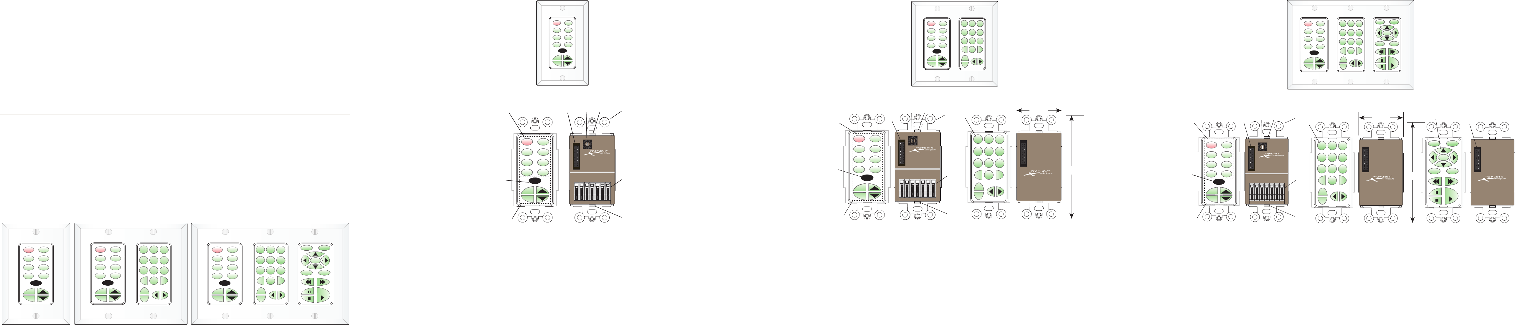
TRIPLE GANG
Figure 6
Triple Gang Set-Up
1. PMKIR Source/Function Buttons – Six of this set
of eight buttons are programmed as source select
for the M4. When the system is off, all buttons have
a background green color. When a source button is
pressed, it turns to a low-level red color to show that
it is the active source and the system is on.
2. Keypad Expansion Terminal – This 16-pin header
terminal is used to inter-connect the optional numeric
and function keypad modules for expansion as
needed. A 3-connector ribbon cable is packed with
each module for making these connections.
3. Address Switch – A unique hex address must be
set for each master keypad when connected on a
common bus within a single zone. Unique addresses
are not required zone-to-zone. It provides up to 16
addresses (0 to F).
4. Snap Tabs – These tabs hold the decorator style
insert panel to the metal mounting plate and are
easily released for custom changing of the buttons.
5. Mounting Plate
– Standard plate allows the
keypad module to be attached to standard in-wall
J-Boxes using the two screws provided. Allows
attachment of standard decorator type cover plates
(also screwless snap-on plates).
6. IR Receiver Lens – Version PMKIR includes
Proficient’s exclusive ANS IR receiver, built-in. It allows
the use of a handheld remote for control of system
components.
7. Connection Terminals – for CAT5 home-run
termination. +Relay and – Relay - for future use.
+12V – Powers the keypad, including the internal IR
receiver on model PMKIR. Includes reverse voltage
protection. Data – Sends IR control signals for
control of system components. GND – Return for
power, IR signal and data. 485 A / 485 B – Balanced,
bi-directional system communications data.
8. Function Buttons
– These lower four buttons (can
be programmed for any function except source select.
9. Numeric and Function Buttons
– Require
programming via Proficient Editor. All buttons glow
background green and can be configured to go off
after a set time, or stay on via Proficient Editor.
Figure 3
The Keypad Gang Configurations
M4 AUDIO CONTROLLER WITH KEYPAD SYSTEM
Keypad Features
The keypads come in four basic modules as shown.
The PMK (13 buttons) and PMKIR (12 buttons) are the
master keypads and must be used in each system.
As mentioned earlier, the M4 comes with a pre-
configured version of the PMKIR, for the convenience
of the installer. It is usable right "out of the box" in
conjunction with a default project that is factory
programmed into the M4. The PMKIR includes an
IR receiver and has one less function button, but is
otherwise identical to the PMK. The PNK Numeric (16
buttons) and PFK Function (14 buttons) keypad modules
can be thought of as “slaves” to the master unit
(they will not work alone), providing additional key
locations for numeric and function commands.
A TYPICAL M4 KEYPAD CONTROLLED SYSTEM
SPKRS
L
R
+
+ –
–
ZONE 4
L R
PRE-OUT
VC
NVC
KEYPAD
IR OUT
L
+
L
-
R
+
R
-
Figure 7