


3-PYRAMID XPA-240/XPA-360/XPA-480 Amplifier Owner’s Manual PYRAMID XPA-240/XPA-360/XPA-480 Amplifier Owner’s Manual-4
Connecting to standard AC power
After making all other connections, set the POWER switch
to OFF position. Then connect the power cord to a standard
AC outlet.
Mounting the amplifier
This amplifier is designed to accept standard rack mounting
installations. Two slots on each end of the front panel make
it suitable for such an installation.
Tightly secure four mounting screws (not supplied) through
these fours slots and into your standard electronics equipment
rack.
Turning the amplifier on
1. Turn on the audio input source equipment which is
connected to the amplifier INPUT jacks.
2. Set the amplifier’s Channel 1 and Channel 2 output level
gain controls to the minimum level settings.
3. Push in the power switch to turn the amplifier on.
Using the power LED meters
The meter pointer position indicates the amplifier output
power. For ease of reading in dark environments, the meter
is illuminated.
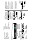
Bridged Mode Operation
This amplifier can operate in a mono bridged output mode, if
your speakers can handle the following power output levels:
XPA-240: 2400 watts
XPA-360: 3600 watts
XPA-480: 4800 watts
As shown in the diagram below, connect the speaker's positive
(+) to the amplifier's red speakers left (1/2) terminals and
negative (-) to red speakers right (1/2) terminals.
The speaker right (+) on the amplifier is used as a negative (-)
terminal for a bridged connection.
Using the Channel 1 and Channel 2 Output Level controls
Rotate output level gain clockwise to increase, or counter-
clockwise to decrease the output power. To get the best
performance with the least sound distortion, always adjust
the output level gain so the meter's pointer does not
continuously exceed the extreme right of the meter's scale.
CAUTION: It is possible to overdrive the amplifier by
setting output level gain too high, which may cause
damage or failure.
About the internal protect circuitry
Special clip circuitry incorporated into your PYRAMID XPA
amplifier’s design protects the amplifier and speaker system
from being damaged from overdriving power.
Under normal conditions, the amplifier’s clip indicator will
flicker as the output power momentarily exceeds the level
as set by the output level gain selector.
However, under excessive output conditions, the protect
indicator lights remain on continuously, alerting you that
the special clip circuitry has become active. When this
occurs, you should simply reduce the output power level
by rotating the Master Volume control counterclockwise.
SWITCH IN “MONO” POSITION
USE
CHANNEL 1
INPUT ONLY
MONO OPERATION
USE
CHANNEL 1
INPUT ONLY
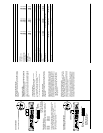
Amplifier Specifications
Input Impedance, balanced (unbalanced)
Continuous Output Power
Stereo Mode
20 Hz to 20 kHz, 8 Ohms
1 kHz, 4 Ohms
Maximum Power, 8 Ohms
Maximum Power, 4 Ohms
Peak Power, 8 Ohms
Bridged Mode
20 Hz to 20 kHz, 8 Ohms
1 kHz, 8 Ohms
Peak Power
THD
at rated output power
Frequency Response
+/– 3 dB
Input Sensitivity
for rated output power
Signal-to-Noise Ratio
A-Weighted
Speaker Impedance
Stereo
Bridged
Power Requirement
Dimensions
H x W x D, inches
(mm)
Weight, lbs (kg)
20 k-Ohms (10 k-Ohms)
170W x 2
220W x 2
230W x 2
260W x 2
1600W x 2
440W x 1
440W x 1
4800W x 1
0.1%
10 Hz to 50 kHz
1.0V
100 dB
4-16 Ohms
8-16 Ohms
3
15/32 x 19 x 10 11/16
(88 x 482 x 271)
20 Ibs (9.1)
XPA-480
20 k-Ohms (10 k-Ohms)
120W x 2
160W x 2
170W x 2
200W x 2
1200W x 2
320W x 1
320W x 1
3600W x 1
0.1%
10 Hz to 50 kHz
1.0V
100 dB
4-16 Ohms
8-16 Ohms
3
15/32 x 19 x 10 11/16
(88 x 482 x 271)
18.5 Ibs (8.4)
XPA-360
20 k-Ohms (10 k-Ohms)
70W x 2
100W x 2
110W x 2
130W x 2
800W x 2
200W x 1
200W x 1
2400W x 1
0.1%
10 Hz to 50 kHz
1.0V
100 dB
4-16 Ohms
8-16 Ohms
3
15/32 x 19 x 10 11/16
(88 x 482 x 271)
16.7 Ibs (7.6)
XPA-240
CAUTION! Do not use
balanced and unbalanced
inputs simultaneously!!
CAUTION! Do not use
balanced and unbalanced
inputs simultaneously!!
CH 2
CH 1
DO NOT USE
BLACK TERMINALS
VOLTAGE
OUTPUTS
CH-2
BRIDGE
CH-1
CH-2
INPUTS
CH-1
GND
POWER CONSUMPTION : 500 W
115/230V-60/50 Hz
~ACiN
FUSE
CH
-
1
CH
-
2
STEREO BRIDGE
MONO
GROUND LIFT
LIFT
BALANCED INPUTS
HOT(+)
COLD(-)
GND
MONO SIGNAL SOURCE
SWITCH IN “BRIDGED” POSITION
MONO BRIDGED OPERATION
120 VAC, 60 Hz / 230 VAC, 50 Hz
VOLTAGE
OUTPUTS
CH-2
BRIDGE
CH-1
CH-2
INPUTS
CH-1
GND
POWER CONSUMPTION : 500 W
115/230V-60/50 Hz
~ACiN
FUSE
CH
-
1
CH
-
2
STEREO BRIDGE
MONO
GROUND LIFT
LIFT
BALANCED INPUTS
HOT(+)
COLD(-)
GND
MONO SIGNAL SOURCE