5
Controls and Connections
The input connector for the CSM is mounted on the bottom side of the enclosure. To gain access to the connectors use the front handle to tilt the
speaker onto the skids located on the flat back side allowing full access to the recessed connector pocket and mode selection switch.
NOTE: Speaker will come from the factory in bi-amp setting.
Input Connectors
The CSM input/output connectors are a pair of Neutrik NL4’s wired in parallel which allows for multi speaker mixes. See (Table 1) for bi-amp
connection. See (Table 2) for full-range connection.
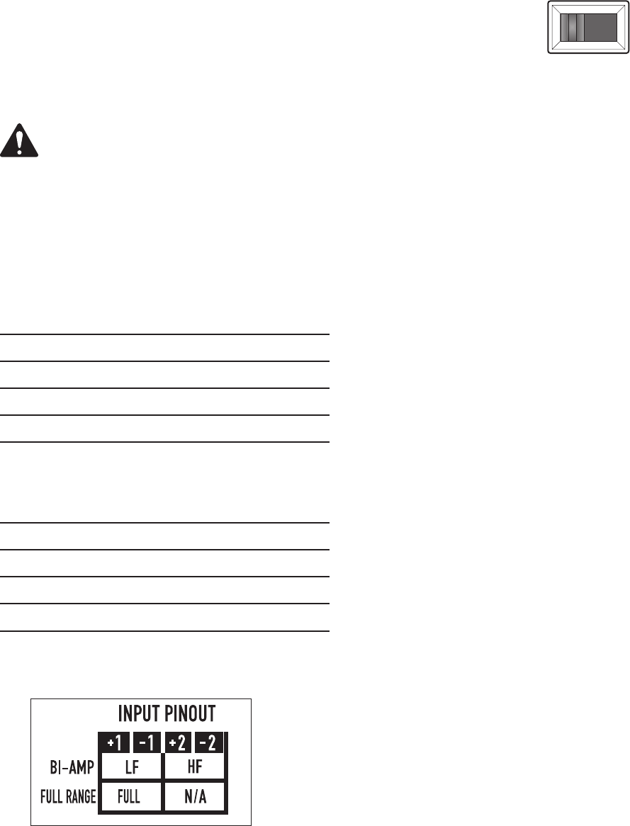
Table 1: Bi-amp Connector Pinout
Table 2: Full-Range Connector Pinout
Pinout Table as printed on CSM input plate label
Mode Selection Switch
Located on the input plate housing is the Mode selection switch (Figure 3). This will
allow the speaker to go from bi-amp to full-range.
To select the mode, orient speaker so the back side is facing you. Insert a standard flat
screwdriver into available slot and slide left for full-range and right for bi-amp.
PIN
Connection
1+ Low-frequency Transducer + (8 Ohms)
1- Low-frequency Transducer - (8 Ohms)
2+ High-frequency Transducer + (8 Ohms)
2- High-frequency Transducer + (8 Ohms)
PIN
Connection
1+ Full-range
1- Full-range
2+ Thru
2- Thru
MODE Selection Switch
BI AMP
FULL RANGE
– Figure 3 –


