3ISA0001
unsolder and remove it. Install and solder a new zener diode oriented in the
same direction. Do the same with diode D210.
11. Check your work. Don’t reattach the channel module assembly and heat sink to
the chassis yet. Instead, continue with the bias and current-limit calibration.
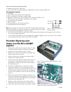
New 4.7-volt zener
Old 5.6-volt zener
snoitarbilaC tsujdA
&054ASI
T005ASI
&057ASI
T008ASI
741RssorcaegatlovCD:saib1lennahC131RV21.0V70.0
42RssorcaegatlovCD:saib2lennahC7132RV21.0V70.0
daoldetrohsotnitnerructuptuO
041R&931R:1lennahC
042R&932R:2lennahC
A5–4A9–5.8
*daoldetrohsgnivirdnehwtnerrucCA
041R&931R:1lennahC
042R&932R:2lennahC
A5.5–5.4A5.6–5.5
)SMR(smho2otniegatlovgnippilC
931RtsujdA:1lennahC
yrtemmysrof
932RtsujdA:2lennahC
yrtemmysrof
V5.73–5.33V94–44
)kaep(smho2otniegatlovgnippilC
931RtsujdA:1lennahC
yrtemmysrof
932RtsujdA:2lennahC
yrtemmysrof
V35–4.74V3.96–2.26
;erutarepmettneibmata(*dnamedCAeldI
)tohnehwrehgih
,A4.0
%01±
A6.0,
%01±
.V001rof2.1ybroV032rof5.0ybtnerrucylpitlum;sreifilpmaV021roferanwohsserugiF*
Procedure: Installing new zener diodes in an
ISA 450 or ISA 500T amplifier
1. Disconnect the amplifier from AC and wait at least 10 minutes for internal voltages to bleed down. Remove the top cover.
2. Remove the four screws on the bottom of the amplifier that fasten the heat sink to the chassis.
3. Remove the three screws that attach the channel module assembly to the chassis standoffs.
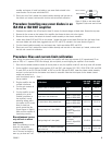
4. Locate zener diodes D107 and D110 on the channel 1 module (the upper circuit board). Bend and trim the leads of two
new zener diodes and solder them piggyback-style to D107 and D110, oriented in the same direction (Figure 4).
5. Turn the channel module assembly over and repeat step 4 with zener diodes D207 and D210.
6. Check your work. Don’t reattach the channel module assembly and heat sink to the chassis yet. Instead, continue with
the bias and current-limit calibration.
Procedure: Bias and current-limit calibration
Note: During the current-limiting part of this procedure, the amplifier will draw high amounts of AC: approximately 22 am-
peres at 120V, or 11 amperes at 230V. Be thorough, but work quickly to avoid tripping the amplifier's circuit breaker.
1. Start with the variable transformer turned all the way down to zero, the amplifier turned off, and its top cover still removed.
2. On the amplifier's circuit boards, locate resistors R147 and R247, and trimpots R131, R231, R139, R239, R140, and R240.
To reach R147 on the ISA 750 and ISA 800T or R247 on the ISA 450 and ISA 500T, rotate the chassis module assembly
and rest it on the heat sink so the bottom circuit board is accessible. Note that the trimpots for the bottom channel
module are located on a
small circuit board next to
the top module.
3. Plug the amplifier into the
variable transformer.
4. Turn the gain controls all
the way down.
5. Turn the amplifier on and
gradually turn up the
variable transformer to
the amplifier's normal
operating voltage while
you monitor its AC current
draw (it should not
grossly exceed the idle
current figures in Table 1).
Make sure the amplifier is
functioning correctly.
Bias adjustment (perform
only with unit at ambient
temperature)
Note: This calibration must be
done with the amplifier
circuitry at ambient tempera-
ture. If the amp has begun to
warm up, you must turn it off
Figure 4. Solder a new zener diode
“piggyback”-style onto each old one.
Table 1.


