12
EN
Channel A
Channel A accepts either microphone or line level inputs. The MIC/LINE IN A inputs can use either a:
• Male XLR connector, or a
• Male 1/4" phone jack (TS or TRS type).
The KW122, KW152, and KW153 feature a 4-position rotary switch (MIC/LINE GAIN) to provide input gain flexibility.
• 0 dB – Regular line level, no additional gain.
• 12 dB – Pre-amp is engaged, primarily for low line levels that need extra gain.
• 24 dB – Pre-amp is engaged and MIC LED illuminates. For direct microphone use.
• 36 dB – Pre-amp is engaged and MIC LED illuminates. For microphones with lower output levels that need extra gain.
The Mic settings (24 and 36 dB) should only be used if a microphone is connected directly to the MIC/LINE IN A. Using the Mic settings for other
purposes may introduce distortion. It is recommended that you move the GAIN A knob to the OFF position, or power down the loudspeaker, before
changing the MIC/LINE GAIN switch. If you change the switch while audio is being processed there will be very noticeable changes in the output level.
The gain for signal delivered on Channel A is set using the GAIN A knob. This control sets the sensitivity of Channel A, as well as the amount of signal
sent to the power amplifier and, in turn, to the loudspeaker components. It also sets the amount of signal sent to the LINE OUT (POST-GAIN MIX).
The green SIGNAL LED illuminates when a signal is present, regardless of the amount of gain set by the GAIN knob. If the LED does not illuminate,
the input is not receiving any signal or the level of the signal is too low; check all connections and the status of the device delivering the signal.
Channel B
Channel B accepts line level input only. The Line Level inputs can use either a:
• Male XLR connector, a
• Male 1/4" phone jack (TS or TRS type), or a
• Mono or stereo line level input on a pair of RCA (phono) jacks. Stereo input received at the RCA input jacks is summed to mono, and is not
passed to the discrete outputs.
The gain for signal delivered on Channel B is set using the GAIN B knob. This control sets the sensitivity of Channel B, as well as the amount of signal
sent to the power amplifier and, in turn, to the loudspeaker components. It also sets the amount of signal sent to the LINE OUT (POST-GAIN MIX).
The green SIGNAL LED illuminates when a signal is present, regardless of the amount of gain set by the GAIN knob. If the LED does not illuminate,
the input is not receiving any signal or the level of the signal is significantly low; check all connections and the status of the device delivering the signal.
Note: Unless the gain controls associated with all active inputs are set to 0 dB, the output signal from the LINE OUT (POST-GAIN MIX) will not be at
the same level as the input signal. If a “slave” speaker is intended to playback at the same level as the “master” speaker, the gain control on the “slave”
speaker should be set to 0 dB.
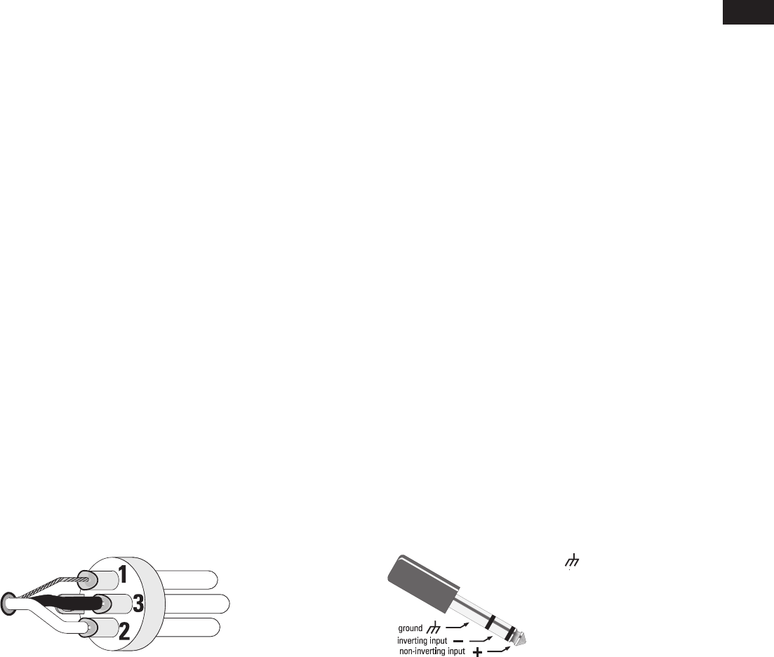
Balanced Inputs
Connect to the plug as shown.
1 = Shield (ground)
2 = Plus (+)
3 = Minus (-)
Ground
— Inverting Input
+ Non-inverting Input
Balanced Inputs XLR Connector
Balanced Inputs ¼" Phone Jack Connector


