


1. If you have not done so already, disconnect the cable from your vehicle’s negative (–) battery terminal.
2. Route the supplied red power cable from the amplifier to your vehicle’s battery.
3. Slide the supplied split tubing onto the exposed red power cable, leaving about 12 inches (30.5 cm) of cable exposed near the battery. Then secure the split tubing inside the
engine compartment using some of the supplied wire tie.
4. Cut the red power cable about 8 to 12 inches (20.3 to 30.5 cm) from the end near the battery, and then slide the wide end of one of the supplied red vinyl insulator boots onto
the short piece of cable. Leave about 1 inch (2.5 cm) cable exposed above the boot.
5. Strip about
1
/2 inch (1.3 cm) of insulation from the end of the short piece of cable near the boot, and then twist the wire so it will fit into the small end of one of the supplied ring
terminals. Then insert the wire inside the ring terminal. Use a wire crimper to crimp the terminal, and slide the boot over the terminal so it covers the joint.
6. Disassemble the fuse holder by unscrewing and removing both of its end caps. Then slide both terminals out of the clear tube of the fuse holder.
7. Strip about
1
/2 inch (1.3 cm) of insulation from the other end of the short piece of cable. Twist the bare wire and insert it into one of the detached end cap.
8. Use a
1
/8 inch hex key to loosen the screw at both terminals, and insert the short piece of cable into the fuse terminal and below the screw. Then tighten the screw to fasten the
cable in place.
9. Repeat Steps 7 and 8 to connect the cable to the fuse holder for the other end.
Caution: Make sure there is no fuse inside the fuse holder before continuing.
10. Connect the red power cable to your vehicle’s positive (+) battery terminal. Then tighten the terminal.
Caution: Due to the high current requirement for most amplifiers, you must connect the red power cable directly to the vehicle’s positive (+) battery terminal or damage to your
vehicle’s wiring could result.
11. Slide the wide end of the other red vinyl insulator boot onto the other end of the long piece of cable (near the amplifier), then repeat Step 5 to attach one of the supplied spade
terminals to the cable.
12. Follow the steps in the amplifier’s user’s guide to attach the red power cable to the amplifier.
Connecting the Power Cable
1. According to the distance between the speaker and amplifier, cut the supplied 40 feet speaker
wire into the required pieces and length.
Note: You might need to remove the door sill, lift the carpet, and route the speaker wires to the
speaker mounting locations. Use the supplied wire ties to secure wire properly, if necessary. Keep
wires away from moving parts or sharp edges to avoid pinching or cutting. If the speakers are being
installed in the doors, carefully route the wire through the door grommets. If the grommets are not
available, buy suitable ones. Then, drill two
1
/2 inch holes for inserting the grommets or split tubing.
2. Strip
1
/2 inch of insulation on each speaker wire. Crimp the insulated speaker terminal (usually
included with speakers) on the positive speaker wire (marked with RadioShack logo) and
negative speaker wire (without marking).
Connect the positive (+) speaker wire’s terminals to the amplifier’s and speaker’s positive (+) speaker
terminals, and the negative (–) speaker wire terminals to the amplifier’s and speaker’s negative (–)
speaker terminals.
Connecting Speakers
1. Slide the wide end of one of the supplied black vinyl insulator boots onto one end of the supplied black ground cable, leaving about 1 inch (2.5 cm) of cable exposed above the
boot.
2. Strip about
1
/2 inch (1.3 cm) of insulation from the end of the cable near the boot, and then twist the wire so it will fit into the small end of the other supplied ring terminal. Then
insert the wire inside the small end of the terminal. Use a wire crimper to crimp the terminal, and slide the boot over the terminal so it covers the joint.
3. Slide the wide end of the other black vinyl insulator boot onto the other end of the black ground cable.
4. Connect the black ground cable with the ring terminal to a chassis ground, such as a metal bolt attached to a metal part of the vehicle’s frame. Be sure the bolt is not insulated
from the chassis by a plastic part, then slide the boot over the terminal so it covers the joint.
5. Follow the steps in the amplifier’s user’s guide to attach the other end of the black ground cable to the amplifier.
Connecting the Ground Cable
The stereo interconnect cable supplied with your wiring kit lets you connect an amplifier with two low-level line input jacks to an auto sound system with two low-level line output
jacks. If your amplifier or auto sound system has more than two low-level line jacks, you will need additional cables (available at your local RadioShack store).
Caution: If your auto sound system does not have low-level line output jacks, do not connect the stereo interconnect cable directly to your amplifier. To connect the cable to the
amplifier, you need a line output converter such as RadioShack Cat No. 12-1338 (not supplied).
1. Connect the red (right) and black (left) plugs on the stereo interconnect cable to the output jacks on your auto sound system. Then follow the steps in the amplifier's user's
guide to attach the other end of the cable to the amplifier.
2. Strip about
1
/4 inch (6.35 mm) of insulation from one end of the supplied remote turn-on wire, insert the bare wire inside the small end of a spade terminal (not supplied), then
use a wire crimper to crimp the terminal.
3. Follow the steps in your auto sound system's and amplifier's user's guide to connect the blue remote turn-on wire to your auto sound system's switched power lead and to the
amplifier.
4. Follow the steps in the amplifier's user's guide to connect your speakers to the amplifier.
Connecting the Stereo Interconnect & Remote Turn-On
This product is warranted by RadioShack against manufacturing defects in material and workmanship under normal use for ninety (90) days from the date of purchase from RadioShack company-owned stores and authorized RadioShack franchisees and dealers. EXCEPT AS PROVIDED HEREIN, RadioShack MAKES NO EXPRESS WARRANTIES AND ANY IMPLIED WARRANTIES,
INCLUDING THOSE OF MERCHANTABILITY AND FITNESS FOR A PARTICULAR PURPOSE, ARE LIMITED IN DURATION TO THE DURATION OF THE WRITTEN LIMITED WARRANTIES CONTAINED HEREIN. EXCEPT AS PROVIDED HEREIN, RadioShack SHALL HAVE NO LIABILITY OR RESPONSIBILITY TO CUSTOMER OR ANY OTHER PERSON OR ENTITY WITH RESPECT
TO ANY LIABILITY, LOSS OR DAMAGE CAUSED DIRECTLY OR INDIRECTLY BY USE OR PERFORMANCE OF THE PRODUCT OR ARISING OUT OF ANY BREACH OF THIS WARRANTY, INCLUDING, BUT NOT LIMITED TO, ANY DAMAGES RESULTING FROM INCONVENIENCE, LOSS OF TIME, DATA, PROPERTY, REVENUE, OR PROFIT OR ANY INDIRECT, SPECIAL,
INCIDENTAL, OR CONSEQUENTIAL DAMAGES, EVEN IF RadioShack HAS BEEN ADVISED OF THE POSSIBILITY OF SUCH DAMAGES.
Some states do not allow limitations on how long an implied warranty lasts or the exclusion or limitation of incidental or consequential damages, so the above limitations or exclusions may not apply to you.
In the event of a product defect during the warranty period, take the product and the RadioShack sales receipt as proof of purchase date to any RadioShack store. RadioShack will, at its option, unless otherwise provided by law: (a) correct the defect by product repair without charge for parts and labor; (b) replace the product with one of the same or similar design; or (c) refund the purchase price.
All replaced parts and products, and products on which a refund is made, become the property of RadioShack. New or reconditioned parts and products may be used in the performance of warranty service. Repaired or replaced parts and products are warranted for the remainder of the original warranty period. You will be charged for repair or replacement of the product made after the expiration
of the warranty period.
This warranty does not cover: (a) damage or failure caused by or attributable to acts of God, abuse, accident, misuse, improper or abnormal usage, failure to follow instructions, improper installation or maintenance, alteration, lightning or other incidence of excess voltage or current; (b) any repairs other than those provided by a RadioShack Authorized Service Facility; (c) consumables such as
fuses or batteries; (d) cosmetic damage; (e) transportation, shipping or insurance costs; or (f) costs of product removal, installation, set-up service adjustment or reinstallation.
This warranty gives you specific legal rights, and you may also have other rights which vary from state to state
RadioShack Customer Relations, 200 Taylor Street, 6th Floor, Fort Worth, TX 76102 12/99
Limited Ninety Day Warranty
©2004 RadioShack Corporation. 270-4128
All Rights Reserved. Printed in Taiwan
RadioShack and RadioShack.com are trademarks 03A04
used by RadioShack Corporation.
Completing the Connections
1. Make sure you have securely made all other connections. Then put the fuse into one of the fuse
terminals. Attach the other fuse terminal onto the fuse, and then slide the fuse holder tube so it
wraps the fuse in the center. Mount the two end caps on the fuse holder and then mount the fuse
holder on a safety location.
2. Reconnect the cable to vehicle's negative (–) battery terminal.
TESTING THE CONNECTIONS
Turn on your vehicle's ignition and make sure the amplifier and auto sound system work properly. If
they do not work, immediately disconnect the cable from your vehicle's negative (–) battery terminal.
Then recheck your connections.
Completing & Testing the Connections
If your amplifier or auto sound equipment does not operate, you might need to replace the red power
cable's fuse. You can check if the fuse is blown or not through the transparent fuse holder. If it is
blown, replace the fuse as under:
Caution: Do not use a fuse with ratings other than those specified here. Doing so might damage your
amplifier.
1. Disconnect the cable from the vehicle's negative (–) battery terminal.
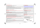
2. Remove one of the fuse holder’s end cap to expose one end of the fuse terminal, then pull one of
the fuse terminal apart from the fuse, then pull the fuse out.
3. Replace the fuse with only a gold-plated glass fuse (Cat No. 270- 1126). The fuse must be no
greater than 60 amps (refer to your amplifier’s user guide).
4. Replace the detached fuse terminal and end cap, make sure the fuse terminal and end cap are
securely mounted. Mount the fuse holder to its original place, if you have mounted it.
5. Reconnect the cable to the vehicle's negative (–) battery terminal.
Replacing the Fuse
Fuse
End Cap
270-4128 080204.fm Page 2 Monday, August 2, 2004 2:26 PM