


7. If you have not yet done so, remove the front cover
(complete with control knob) of the unit by undoing
the retaining screws at the top and bottom of the
unit and lifting the cover off. The top-fixing hole is a
keyhole slot, and should be marked and drilled
first. Tighten top screw with head protruding about
10mm from wall and hook the back-plate over the
screw head. This allows for correct and accurate
alignment of your shower before marking and fixing
the bottom/side position. You may not wish to
tighten up all 3 screws at this stage as the holes
are elongated to allow for adjustment after other
connections have taken place.
WARNING! TAKE CARE NOT TO DAMAGE THE
PRINTED CIRCUIT BOARD IN ANY WAY. DURING
INSTALLATION AVOID DUST AND DEBRIS
GETTING ON IT.
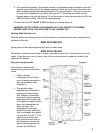
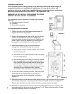
8. Do not obstruct the pressure relief device found in
the back-plate slot underneath the outlet
connection (see diagram 2). Especially if silicone
sealant or similar materials are used around the
edges of the back-plate.
9. There are a number of clearly marked shields in
the shower unit. These are important for the correct operation of this shower and MUST
NOT be removed under any circumstances.
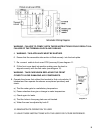
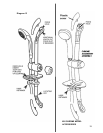
b) Plumbing (see diagram 9)
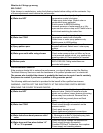
The heater should be connected to the mains cold water supply. This must have a minimum
running pressure of 100kPa, 1.0 bar (14.5 p.s.i) and a maximum pressure of 1000kPa, 10
bar (145 p.s.i).
Before connecting the pipe-work to the shower ensure that pipe-work is flushed out.
1. It is recommended that a WRAS (Water Regulations Advisory Scheme) listed isolating
valve is fitted between the rising main and the unit. This will allow the unit to be serviced
without turning off the cold water or exchanged without having to turn off the water at the
water mains stop valve.
2. The heater can be fed from a header tank provided this has a minimum head height of
10.5 metres (35ft).
3. 15mm copper or stainless steel pipe should be used alongside with a standard
compression fitting. In multiple shower installations correct pipe-work sizes should be
calculated to maintain adequate flow to each shower.
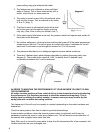
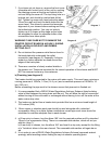
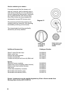
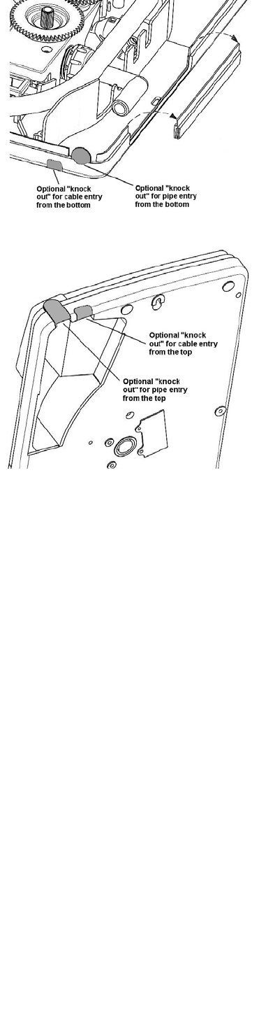
4. a) If top entry is chosen, turn the elbow 180° into the required position and fit a standard
15mm in line compression fitting. There is a removable side section, which will aid you
with this (diag.7).
b) If rear entry is chosen, turn the elbow 180° and treat it as top entry except for the fitting
of a ‘Yorkshire’ elbow in the rear channel. The removable side section will again be an
aid.
5. It is in order to use a WRAS (Water Regulations Advisory Scheme) approved sealant
sparingly whilst avoiding excess finding its way into shower operating parts.
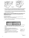
Diagram 7
Diagram 8
7