


4
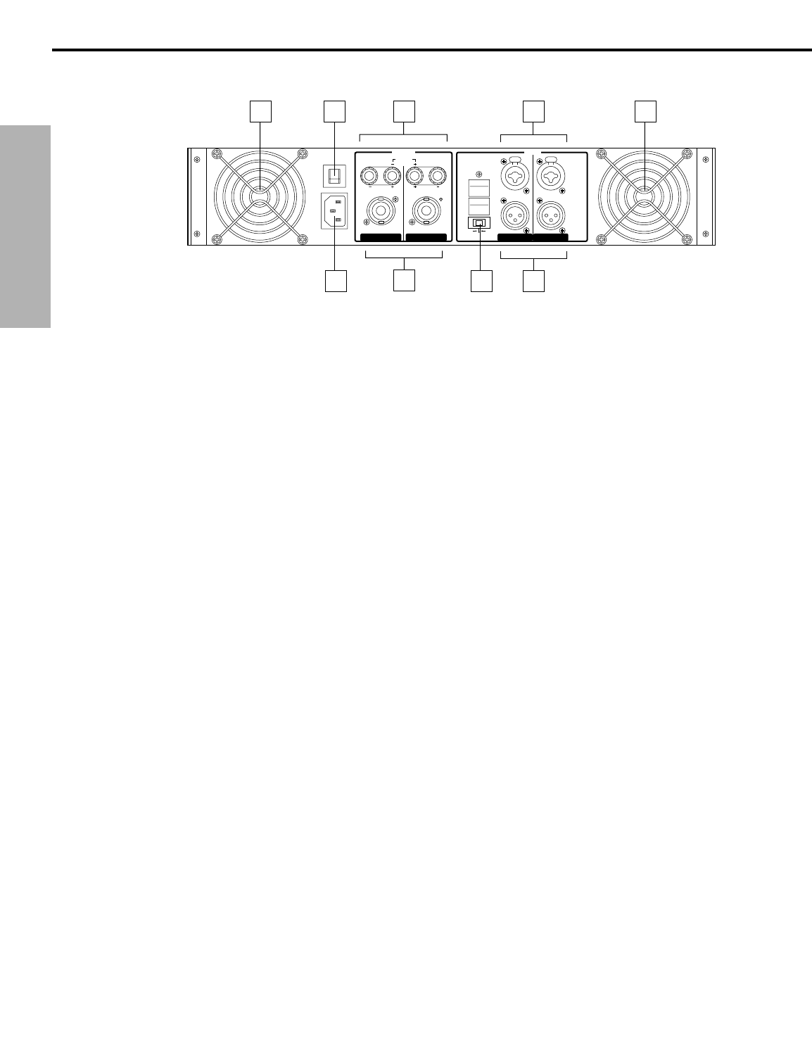
Guided Tour - Rear Panel
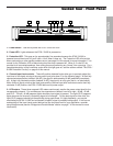
1: Fan - This variable-speed fan provides vital cooling to your S700 / S1000 (the hotter the amp gets,
the faster the fan blows!). Make sure that both the front and rear panels are kept free of all obstructions
and that cool, fresh air is accessible at all times. Also, try to ensure that the S700 / S1000 is used in a
dust-free environment.
2: Circuit Breaker - This circuit breaker will trip if there is a fault with the mains voltage or if maximum
output is exceeded (very highly distorted). Push it in (once only!) to restart the amplifier.
3: AC input - Connect the supplied heavy-gauge 3-pin “IEC” power cable here.
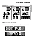
4: Banana output connectors - Use these to connect each channel of the S700 / S1000 to 4- or 8-ohm
loudspeakers. Be sure to connect the loudspeaker correctly, with the red (+) terminal normally
connected to the positive input of the speaker and the black (ground) terminal normally connected to the
negative input of the speaker. See page 7 in this manual for more information about Bridged mode and
pages 8 and 9 in this manual for full speaker connection instructions.
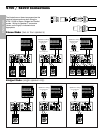
5: Speakon™ output connectors - Alternatively, you can use these to connect each channel of the
S700 / S1000 to 4- or 8-ohm loudspeakers. See page 7 in this manual for more information about
Bridged mode and pages 8 and 9 in this manual for full Speakon™ connector wiring and interconnection
instructions.
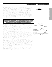
6: Bridged / Stereo / Parallel switch - For normal operation, place this three-way switch in its center
(“STEREO”) position. When placed in its right (“PARALLEL”) position, the signal arriving at the
Channel 1 input only is routed to the power amplifiers of both Channel 1 and Channel 2 (the Channel 2
input is ignored), with each power amplifier delivering 350 watts into 4 ohms (in the case of the S700) or
500 watts into 4 ohms (in the case of the S1000). When placed in its left (“BRIDGED”) position, the
signal arriving at the Channel 1 input only is again routed to both power amplifiers (again, the Channel 2
input is ignored), but the two power amplifiers are bridged together, providing a full 700 watts of power
into 8 ohms (in the case of the S700) or a full 1000 watts of power into 8 ohms (in the case of the
S1000). For more information, see the “Bridged and Parallel Modes” section on page 7 in this manual
and the “S700 / S1000 Connections” section on pages 8 -9 in this manual. WARNING: Due to the
extremely high power output of the S700 / S1000 when used in Bridged mode, be sure to use
only loudspeakers sufficiently rated to handle the resultant wattage (in Bridged mode, these
must be 8-ohm speakers).
7: Input connectors - Connect incoming signal to these electronically balanced Combination
connectors, using either XLR or 1/4" TRS (Tip/Ring/Sleeve) plugs, wired as follows: Pin 2 (or Tip) hot,
Pin 3 (or Ring) cold, and Pin 1 (or Sleeve) ground. We recommend the use of balanced three-conductor
cabling wherever possible (unbalanced two-conductor 1/4" plugs can also be inserted into these inputs,
but you’ll get better signal quality and less outside noise and hum if you use balanced lines).
The S700 / S1000 accepts input levels of any strength but needs at least 0 dBu to achieve maximum
power. Stereo signals should be connected to both the Channel 1 and Channel 2 input jacks; however,
when operating the S700 / S1000 in Bridged or Parallel modes, use the Channel 1 input jack only.
See page 7 in this manual for more information about Parallel mode and pages 8 and 9 in this manual
for full interconnection instructions.
8: Link connectors - These XLR connectors provide unity gain outputs, allowing the S700 / S1000 to
be daisy-chained to additional power amplifiers. Wiring is as follows: Pin 2 hot, Pin 3 cold, Pin 1 ground.
See page 9 in this manual for more information.
20A / 250V
PUSH TO RESET
~AC INPUT
120V 60Hz, 770W
BRIDGE
(8Ω~16Ω)
BRIDGED
PARALLEL
STEREO
BALANCED
0dBm
TRS
BALANCED
•TIP=HOT
•RING=COLD
•SLEEVE=GND
XLR
BALANCED
•3=COLD
•2=HOT
•1=GND
BALANCED
0dBm
(4Ω~8Ω) (4Ω~8Ω)
(4Ω~8Ω)
(4Ω~8Ω)
PUSH PUSH
12
A
M
P
CH 2 CH 1 CH 2 CH 1
OUTPUT
INPUT
3
4
2
1
5
1
6
8
7
ENGLISH