


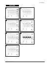

3-1-1 Removing the Stand
1. Remove 4 screws in the hinge area.
2. Disconnect Power Cord and Signal Cable.
3. Pry it off the back of the monitor.
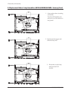
3-1-2 Main Body Disassembly
1. Remove 2 screws on the two corner of the
Rear Cover.
2. Remove Rear Cover from the Front Cover.
3. Remove 4 screws on the Shield and remove
the shield.
4. Disconnect Inverter wire, Function PCB wire
and Interface wire.
Remove 3 screws on the Main PCB and
remove 2 screws on the D sub shield.
5. Remove 3 screws on the power PCB and
remove 2 screws on the Inverter PCB.
6. Remove the Main PCB Assembly.
7. Remove 3 screws on the Function PCB from
locking area of Function knob and remove
Function PCB.
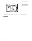
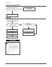
3-1-3 Standard Stand Disassembly
1. Remove 2 screws from the Stand front.
2. Remove 7 screws from the Stand Bottom.
3. Remove Stand Rear from the Stand assembly.
4. Remove 5 screws from the Stand assembly.
5. Remove the Neck front from the Stand
assembly.
6. Remove 2 screws from the Stand assembly.
7. Remove Neck Rear from the Stand assembly.
8. Remove 4 screws from the Stand assembly.
GH15LS/GH15ES/GH15MS 3-1
3 Disassembly and Reassembly
This section of the service manual describes the disassembly and reassembly procedures for the
GH15LS/GH15ES/GH15MS monitor.
WARNING: This monitor contains electrostatically sensitive devices. Use with caution when
handling these components.
3-1 Disassembly
Cautions:1. Disconnect the monitor from the power source before disassembly.
2. Follow these directions carefully; never use metal instruments to pry apart the cabinet.