


4. Service procedures
1
2
3
4
Section
SM830082
IV - 44
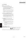
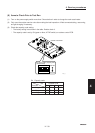
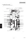
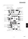
(12) Checking procedure for each PC Board
The indoor and outdoor PCBs have functions to check the signal transmission and reception of the
serial circuit and to check the microcomputer operation. (Self-diagnosis function)
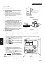
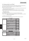
● Precautions required when checking
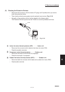
1. After turning off the power to the indoor (outdoor) unit, remove the inter-unit control wiring (U1-U2)
and create a short-circuit between U1 and U2.
2. Short the CHECK PIN on the PC board of the indoor (outdoor) unit and turn on the power.
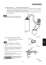
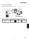
3. When checking the Outdoor controller, remove the compressor wiring from the compressor
electromagnetic contactor.
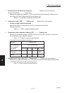
4-1. Checking the serial circuit
Indoor controller: A lighted LED indicates normal. A blinking LED indicates abnormal.
Outdoor controller: Blinking LEDs (D11 and D22) indicate normal. If one of the LEDs (D11 and D22)
goes off, it indicates abnormal.
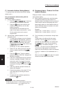
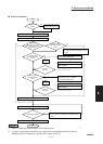
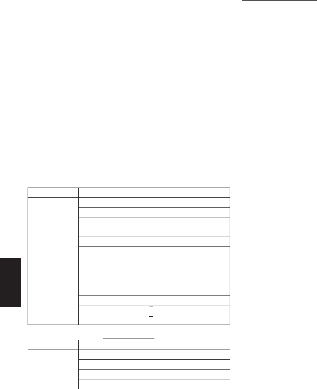
4-2. Checking microcomputer operation
When the microcomputer works normally, the relays are switched in sequence as below.
Output ON time
Indoor fan Very high fan speed (HH) 0.5 seconds
Indoor fan High fan speed (H) 0.5 seconds
Indoor fan Low fan speed (L) 0.5 seconds
Indoor fan Very low fan speed (LL) 0.5 seconds
Flap motor 0.5 seconds
Drain pump 0.5 seconds
Operation order Electric heater 0.5 seconds
Operation signal 0.5 seconds
In a lump 0.5 seconds
Electronic control valve A 0.5 seconds
Electronic control valve B 0.5 seconds
Electronic control valve.A 0.5 seconds
Electronic control valve B 0.5 seconds
Indoor controller
Output ON time
Outdoor fan High fan speed (H) 0.5 seconds
Operation order
Outdoor fan Low fan speed (L) 0.5 seconds
4-way valve 0.5 seconds
Compressor 0.5 seconds
Outdoor controller