


8
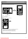
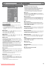
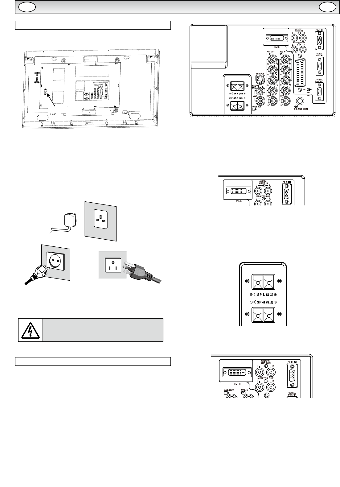
Step: 1 Mains Connection
■ Connect the display unit to VGA, BNC and Scart con-
nector as required.
1. Connect the in-line power connector to the Mains Inlet as shown
above.
2. Connect the power cord of the LCD monitor to a suitable wall outlet.
✐ As this product does not have a mains On/Off switch, please
ensure your mains plug is easily accessible.
✐ The LCD monitor is prepared for a mains voltage AC100 ~ 240V,
50Hz/60Hz. To completely switch off the mains, or when the
display unit is not to be used for an extended period of time, it is
advisable to disconnect the power cord from the power outlet.
✐ Please use the correct mains lead supplied with the set for your
area.
3. Warning:
To prevent injury, the unit must be securely attached to
the wall in accordance with the installation instructions.
WARNING! High voltages are used in the
operation of this set. Refer service to qualied
service personnel.
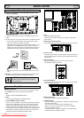
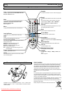
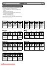
Step: 2 Connections
■ INPUT selection
To switch either AV1, RGB, AV2, AV3, PC, DVI or Network by press-
ing the INPUT button on your remote control repeatedly.
1. AV1
SCART connection/CVBS/RGB/S-VIDEO.
2. RGB
TTL input (5V RGB signals) into SCART terminal.
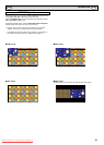
3. Y, Pb, Pr/RGBHV connection (AV2)
Choose Y, Pb, Pr or RGB H/V connection by selecting AV2 Setting
in Set up menu (see page 12). You can connect your DVD player
to the Y, Pb, Pr terminals instead of using a scart lead. This can
support high denition in analogue component form. RGB H/V can
be used as a PC input via the BNC terminals. Both options support
a large range of resolutions (page 19). AV2-OUT can be used to
output the incoming AV2 signal to the other monitor.
4. AV3
Composite (CVBS) signal input.
AV3-OUT can be used to output the incoming AV3 signal to the
other monitor.
5. DVI-D (Digital Video Interface)
DVI-D supports a large range of resolutions as shown on page 19.
6. PC connection
PC input (PC-IN D-SUB). This input supports a large range of reso
-
lutions as shown page 19. Audio can be connected via the 3.5mm
PC-AUDIO IN.
7. External Speaker
Output the audio signal from AV1, AV2, AV3, PC and DVI.
The speaker impedance is 8 ohms.
8. AV2 / DVI AUDIO IN
Connect the audio output (stereo) from a computer or video equip-
ment connected AV2 or DVI.
9. Monitor Audio OUT
This terminals output xed level from AUDIO IN.
10. RS232C IN/OUT
When the monitor is controlled by a computer, connect to this jack
with serial control cable.
You can connect to another monitor with RS232C OUT.
When you connect PC with RS232C, select “ON” at Network
standby in Installation mode.
If it is selected “OFF”, RS232C terminals do not functional. Also
select push button to “SERIAL POART”.
INSTALLATION
Mains Inlet
AC Mains Outlet
GB GB
Downloaded From TV-Manual.com Manuals