4. Service procedures
SM830082
IV - 24
1
2
3
4
Section
5
(D) Check the remote controller itself for correct operation
The remote controller has a self-diagnostic function to check for problems in the remote
controller itself.
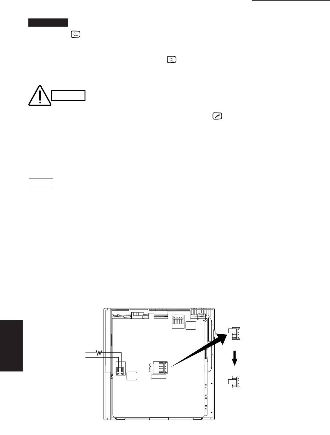
In order to check, the shorting plug (2P) inserted in the socket (4P) on the back of the remote
controller circuit board should be moved from RCU.Main to RCU.CK. (Ref. Fig. IV-6)
● Checking serial communications
The remote controller’s own serial communications sending and receiving circuits can be
checked by moving the shorting plug. The indicators will respond as follows for approximately
10 seconds, then turn off:
Correct : All indicators light up.
Incorrect : All indicators flash on and off.
● Checking I/O circuits
After completing the serial communications check (for 10 seconds), operate each switch on
the remote controller. If the LCD display responds, then the remote controller is normal.
NOTE
1) Be sure that the shorting plug is inserted onto RCU.Main during normal operation.
2) The remote controller self-diagnostic function can be run on a remote controller
independently if power of 9–16 VDC is supplied to plug 2P as shown in Figure IV-6.
(A 12-Ω 1/4-W resistor must be placed in between.)
Never press (clear) button unless you want to erase the accessed data in memory. Follow
the procedure below only when erasing is necessary.
❏ To erase accessed data, press the button.
❏ When erasing is finished,“----” mark appears on the controller’s display.
After checking the alarm messages, be sure to press the button.
Important
CAUTION
Fig. IV-6
During normal
operation
Shorting plug
is moved.
During self-
diagnostic check
2079_M_I
TIMER
TMNL.
RCU
TMNL.
RCU.ADR
RCU.Main
RCU.Sub
RCU.CK
12Ω•1/4W
DC9
~16V


