Multi Room Audio Amplifier Installation Instructions
14
4 Power Supply Connection
The 3.75 Amp-rated power supplies have a power cord and the 1.25 Amp-rated
power supply is a plug-pack design. If you are using a High Temperature Power
Supply with a 560110R Low Power Remote Amplifier, use the cable adapter that is
provided with the power supply. Refer to the appropriate power supply instruction
sheet.
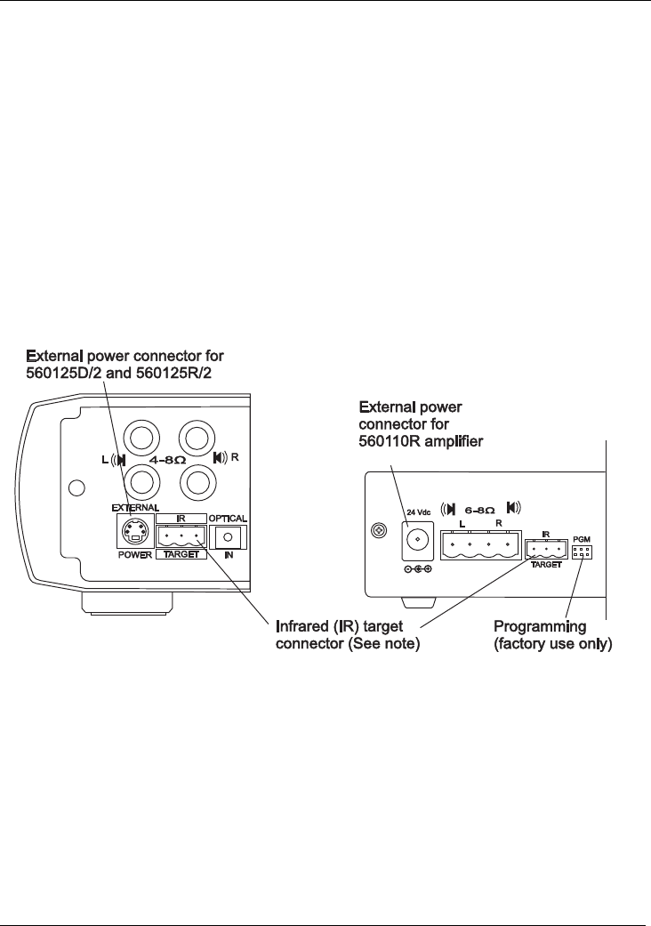
1. Plug the end of the power supply output cable into the External Power
connector on the back panel of the MRA amplifier. Refer to Figure 6.
2. Install the supplied ferrite filter on the power supply cable between the power
supply and the MRA amplifier. The filter halves latch when closed over the cable.
3. After you have connected the C-Bus cable, loudspeakers and audio input,
connect the power supply to a suitable wall power outlet. Refer to the
appropriate sections in this document.
Figure 6. MRA Amplifier External Power connections
Note on Figure 6
The IR Target connectors on the amplifiers' rear panels are used to route IR control
signals back to A/V equipment using the digital audio cables and IR emitters
connected to the Matrix Switcher. Refer to the
C-Bus Matrix Switcher and System
Installation Instructions
for more details.
The programming (PGM) connector is used at the factory to load firmware. The
PGM connector is not used during installation or subsequent operation.


