


8
COMPRESSOR FEATURES
1
2
3
4
5
6
7
8
9
10
11
12
13
14
15
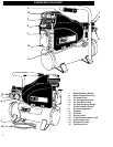
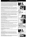
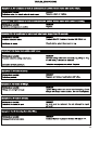
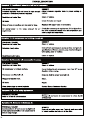
Motor/Pressure Switch
Motor Thermal Overload
Air Intake Filter
Air Compressor Pump
Air Tank Drain Valve
Air Tank Pressure Gauge
Outlet Pressure Gauge
Pressure Regulator
Dipstick
Oil Drain
Delivery tube
115 Volt electric power cord
Quick disconnect
Safety relief valve
Cold start valve
1
11
8
14
2
5
12
3
4
9
10
15
6
7
13
9
COMPRESSOR FEATURES
1
2
3
4
5
9
10
11
12
15
13
14
8
7
6
1) MOTOR/PRESSURE SWITCH: This switch is used to start or stop the air
compressor. Moving the switch to the "Auto" (On) position will provide automatic power
to the pressure switch which will allow the motor to start when the air tank pressure is
below the factory set "cut-in" pressure. When in the On Position, the pressure switch
stops the motor when the air tank pressure reaches the factory set "cut-out" pressure.
For safety purposes, this switch also has a pressure release valve located below the
switch designed to automatically release compressed air from the air compressor pump
head and its discharge line when the air compressor reaches "cut-out" pressure or is
shut off. This allows the motor to restart freely. Moving the switch to the "Off" position
will remove power from the motor and stop the air compressor.
2) MOTOR THERMA L OVERLOAD: The electric motor ha s a manual resettable
overload protector. If the mot or draws excessive current for any reason, the thermal
overload will cut off power, thus preventing the motor from being damaged. Wait until
the motor is cool before pressing the reset button to begin working again. If multiple
reset result in consistent trips, check service and/or reference extension cord sizing
recommendations.
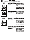
3) AIR INTAKE FILTER: This filter is designed to clean air coming into the pump. To
ensure the pump continually receives a clean, cool, dry air supply this filter must always be
clean and ventilation opening free from obstructions. The filter can be removed for cleaning
by using warm, soapy water. Rinse the filter and air dry. Replace filter when necessary.
4) AIR COMPRESSOR PUMP: To compress air, the piston moves up and down in the
cylinder. On the downstroke, air is drawn in through the air intake valve while the
exhaust valve remains closed. On the upstroke, air is compressed, the intake valve
closes and compressed air is forced out through the exhaust valve, into the discharge
line, through the check valve and into the air tank.
5) AIR TANK DRAIN VALVE: The drain valve is used to remove moisture from the air
tank(s) after the air compressor is shut off. NEVER attempt to open the drain valve
when more than 10 PSI of air pressure is in the air tank! To open the drain valve,
turn the knob counterclockwise.
6) AIR TANK PRESSURE GAUGE: The air tank pressure gauge indicates the reserve air
pressure in the air tank (s).
7) OUTLET PRESSURE GAUGE: The outlet pressure gauge indicates the air pressure
available at the outlet side of the regulator. This pressure is controlled by the regulator and
is always less or equal to the air tank pressure.
8) PRESSURE REGULATOR: The air pressure coming from the air tank is controlled by
the regulator knob. Turn the pressure regulation knob clockwise to i ncrease discharge
pressure, and counterclockwise to de crease d ischarge pressure.
9) OIL DIPSTICK: Th e dipstick will register the amount o f oil in the pump. Oil level
should be ch ecked on a daily basis to ensure that it does not exceed the maximum notch
or fall b elow the minimum notch on th e dipstick. Air escaping from the vent is normal.
10) OIL DRAIN: Th e drain is provided to r emove oil that has exceeded its service life.
Drain oil into approved container and dispose of properly. Re fill prior to starting.
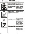
11) RISK OF BURNS Head and discharge lines can be very hot.
Do not touch until unit has cooled after use.
12) POWER CORD: Use only 115VAC 15A service. See extension cord recommendations
on page 10.
13) QUICK DISCONNECT: Spring loaded sealed coupling for easy hose removal. 1/4".
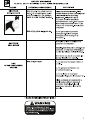
14) SAFETY RELIEF VALVE: This valve is designed to prevent system failures by
relieving pressure from the system if compressed air reaches a predeterminedlevel. The
valve is preset by the manufacturer and must not be modified in any way. To verify the
valve is working properly, pull on the ring. Air pressure should escape. When the ring is
released, it will reseat.
15) COLD START VALVE: The compressor is provided with a normally open valve. This
valve will relieve compressed air for a few seconds at compressor start up allowing the
motor to reach operating speed with low pump resistance.