


-
2
- -
3
-
1
Make sure the LCD Monitor stand is secured with
anchor bolts.
2
Insert the hooks of the hoisting device into the eye
bolts of the LCD Monitor and slightly lift the monitor.
Lift up the monitor so that the hoisting chains become
taut.
•
3
Remove the stand mounting bolts on the rear and
detach the LCD Monitor from the stand.
Loosen the 8 bolts gradually and evenly.
If it is difcult to loosen the bolts, lift the monitor up
slightly with the hoisting device to reduce the load on
the bolts.
Check the hoisting condition frequently to prevent the
LCD Monitor from falling.
•
•
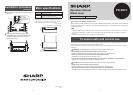
Supplied accessories
Conrm that the following accessories have been provided with the product.
□
Support rod x 2
□
M8 bolt x 4
□
M8 spring washer x 4
□
M8 plain washer x 4
□
Left and right base reinforcement
angles (x 1 each)
□
Left and right cover mounting
angles (x 1 each)
□
Front and rear base plates (x 1 each)
□
Front cover x 1
□
Extension front cover x 1
□
Left and right back covers (x 1 each)
□
Cover reinforcement angle x 1
□
M6 screw x 56
□
Cable clamp x 4
□
Operation manual (this manual)
Precautions on use
The installation, removal, or transportation of the LCD Monitor must be performed by qualied service personnel.
The LCD Monitor is large and heavy. Installation requires special knowledge and qualications.
Customers should not attempt to install, remove, or transport the LCD Monitor by themselves.
SHARP shall have no liability for any accidents or damages caused by improper installation or mishandling.
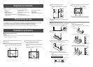
Installation procedure
n
Mounting support rods
Caution
The LCD Monitor is large and heavy. It must be moved with a hoisting device (chain block, etc.).
Installation requires at least four people.
•
•
•
•
•
4
Mount the support rods to the stand.
Mount using the supplied M8 bolts.
The support rods can be mounted at two different
heights.
1600 mm*
(63 inch)
1500 mm*
(59
1
/
16
inch)
Spring
washer
Plain
washer
*Height to center of the LCD Monitor
5
Hoist to the height where the LCD Monitor is to be
mounted.
•
•
n
Mounting stand cover
1
Attach the base reinforcement angle (L and R) to the
stand of the monitor with 6 supplied M6 screws.
Base
reinforcement angle
2
Attach the front base plate with 3 supplied M6
screws.
Front base plate
3
Attach the rear base plate, then the cover mounting
angle (L and R) with 9 supplied M6 screws.
Rear base plate
Cover mounting
angle
4
Attach the front cover with the top edge up.
Turn the front cover over if the screw holes are not
aligned.
Make sure that the front cover does not scrape against
the base plates to prevent scratching.
Front cover mounting procedure
Fit one side of the front cover over the cover mounting angle
(1), then t the other side while pulling outwards (2, 3, 4).
1
2
3
4
•
•
6
Mount the LCD Monitor to the stand (and support
rods) using the bolts removed in step 3.
Spring washer
Plain washer
7
Conrm that the LCD Monitor is mounted securely,
and then remove the hooks of the hoisting device.
[Step 4 continued]
When height is 1600 mm (63 inch)
(1) Attach the extension front cover with 4 supplied M6
screws.
Extension front
cover
(2) Attach the front cover with 8 supplied M6 screws.
*Rear side of front cover
Front cover
When height is 1500 mm (59 1/16 inch)
(1) Attach the front cover with 10 supplied M6 screws.
Front cover
*Rear side of front cover
•
•