


5
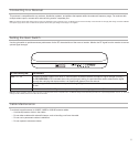
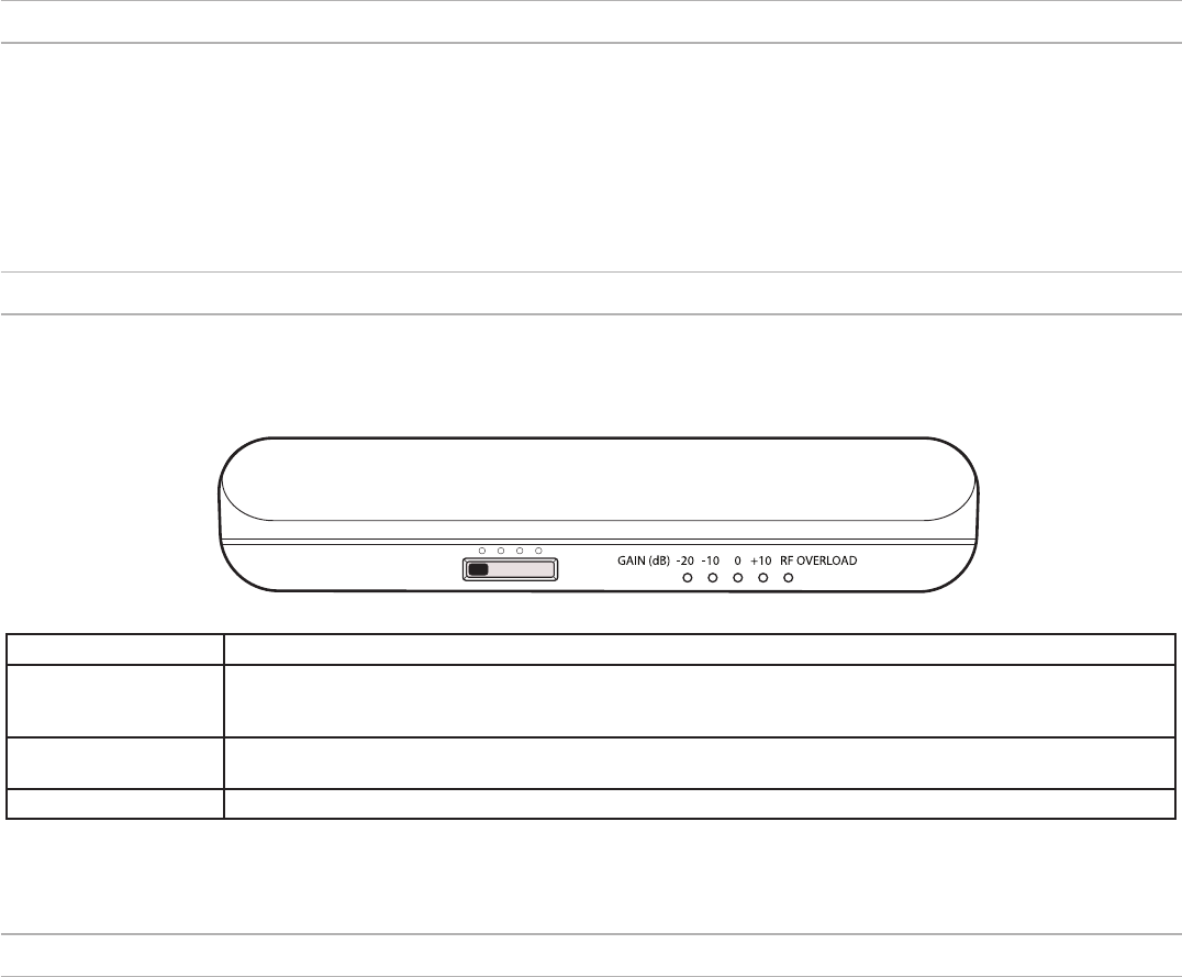
Setting the Gain Switch
Use the gain switch to optimize antenna performance for the RF characteristics of the room or location. Monitor the RF signal from the receiver to ensure
optimal signal strength.
Cable Maintenance
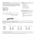
To maintain top performance for UA825, UA850 or UA8100 antenna cables:
• Avoid sharp bends or kinks in the cables.
• Do not deform cables with makeshift clamps, such as bending a nail over the cable.
• Do not use in permanent outdoor installations.
• Do not expose to extreme moisture.
RF Gain Setting (dB) Use Scenario
Pad: −10, −20 Provides increased isolation from other RF sources when the desired wireless microphone signal strength is strong. If
the RF OVERLOAD LED illuminates when using a higher gain setting, the pad should be used to attenuate the signal,
but only after verifying that the transmitter is an appropriate distance from the antenna.
0 (Default) Suitable for typical room installations and provides enough RF gain in most cases when cable runs are between 10 and
50 feet.
Boost: +10 Provides an extra 10 dB of RF gain to compensate for signal loss if using long cable runs (50 feet or more).
Note: Bias power supplied by receiver antenna ports or an external power source is required for the +10 dB boost setting and for illuminating the LEDs. For un-powered applications, the -20, -10, and 0 dB
settings are still functional; however, the LEDs will not illuminate.
Connecting to a Receiver
This antenna is compatible with any receivers, distribution systems, and splitters that operate within the antenna's frequency range. For receivers with
multiple antenna ports, connect each antenna being used to a separate port.
Note: The antenna requires bias voltage from the receiver or distribution system to operate on the +10 dB setting and for LED functionality. If these devices do not supply bias voltage, the Shure UABIAST
inline power supply can be used. The antenna still operates with all other gain settings if bias voltage is not supplied.