


L
R
AUDIO
OUT
REAR
AUDIO
OUT
FRONT
BUS
AUDIO
IN
3
1
2
4
5
6
7
AUDIO OUT
FRONT
BUS AUDIO IN
/AUX IN
*
2
BUS
CONTROL IN
REMOTE
IN
AUDIO OUT
REAR
SUB OUT (MONO)
© 2007 Sony Corporation Printed in Taiwan
3-276-519-41 (1)
Cautions
Be sure to install this unit in the dashboard of the car
as the rear side of the unit becomes hot during use.
• This unit is designed for negative earth 12 V DC
operation only.
• Do not get the leads under a screw, or caught in moving
parts (e.g. seat railing).
• Before making connections, turn the car ignition off to
avoid short circuits.
• Connect the yellow and red power input leads only
after all other leads have been connected.
• Run all earth leads to a common earth point.
• Be sure to in su late any loose un con nect ed leads with
electrical tape for safety.
• Do not cover the ventilation slots or heat sinks of the
unit.
Notes on the power supply lead (yellow)
• When connecting this unit in combination with other
stereo components, the connected car circuit’s rating
must be higher than the sum of each component’s fuse.
• When no car circuits are rated high enough, connect
the unit directly to the battery.
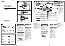
Parts Iist
• The numbers in the list are keyed to those in the
instructions.
• The bracket and the protection collar are
attached to the unit before shipping. Before mounting
the unit, use the release keys to remove the bracket
and the protection collar from the unit. For
details, see “Removing the protection collar and the
bracket ()” on the reverse side of the sheet.
• Keep the release keys for future use as they
are also necessary if you remove the unit from
your car.
Caution
Handle the bracket carefully to avoid injuring your
fi ngers.
Catch
Note
Before installing, make sure that the catches on both sides of
the bracket are bent inwards 2 mm. If the catches are straight
or bent outwards, the unit will not be installed securely and may
spring out.
Installation/Connections
⫭塁濊䴾嵓徇㌉
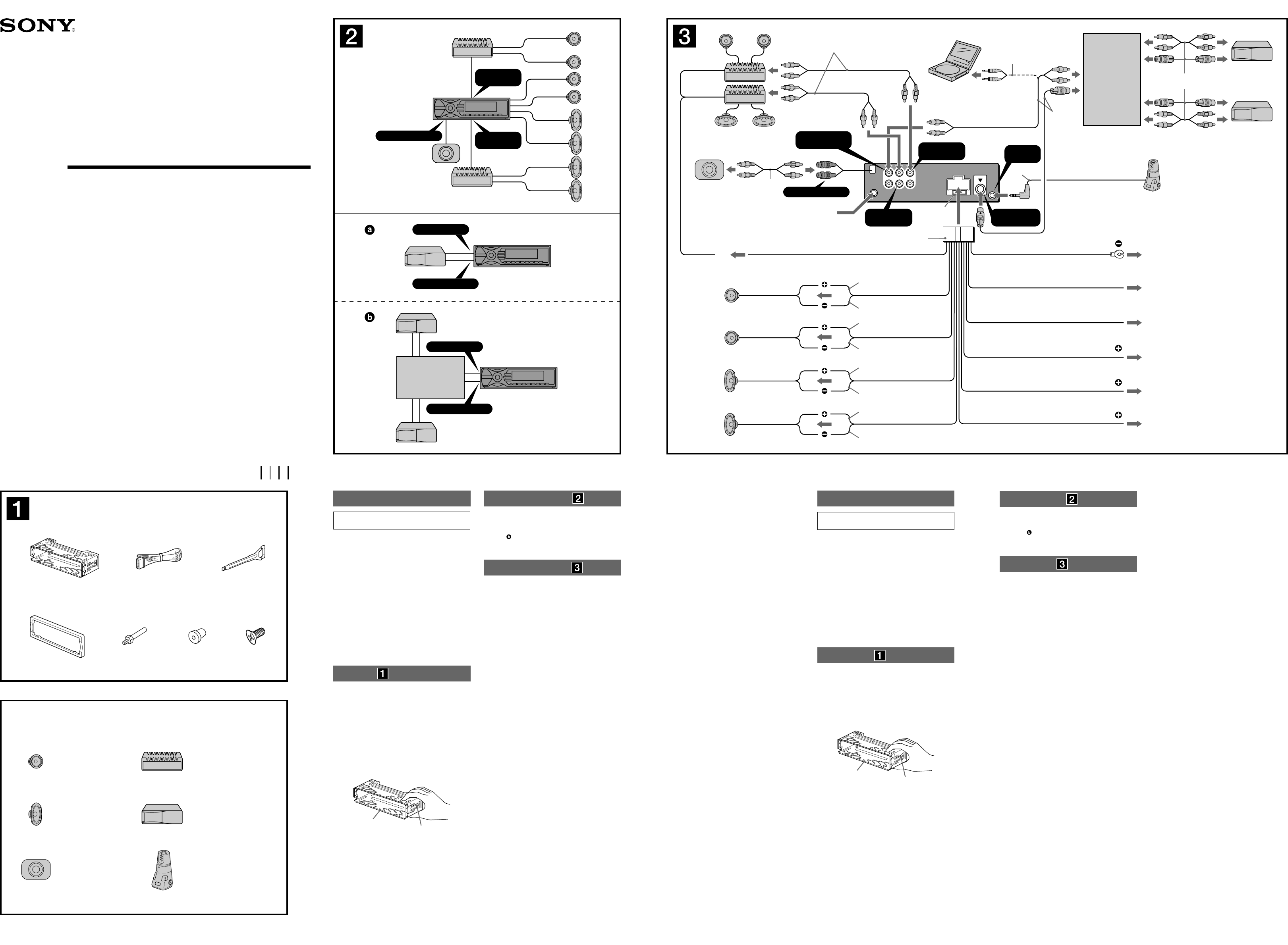
Connection example
Notes (-
A
)
• Be sure to connect the earth lead before connecting the
amplifi er.
• The alarm will only sound if the built-in amplifi er is used.
Tip (-
B
-
)
For connecting two or more CD/MD changers, the source
selector XA-C40 (not supplied) is necessary.
Connection diagram
To a metal surface of the car
First connect the black earth lead, then connect the orange/
white stripped, yellow, and red power input leads.
To the power aerial control lead or power
supply lead of aerial booster amplifi er
Notes
• It is not necessary to connect this lead if there is no power
aerial or aerial booster, or with a manually-operated
telescopic aerial.
• When your car has a built-in FM/AM aerial in the rear/side
glass, see “Notes on the control and power supply leads.”
To AMP REMOTE IN of an optional power
amplifi er
This connection is only for amplifi ers. Connecting any other
system may damage the unit.
To the interface cable of a car telephone
To a car’s illumination signal
Be sure to connect the black earth lead to a metal surface
of the car fi rst.
To the +12 V power terminal which is
energized in the accessory position of the
ignition key switch
Notes
• If there is no accessory position, connect to the +12 V
power (battery) terminal which is energized at all times.
Be sure to connect the black earth lead to a metal surface
of the car fi rst.
• When your car has a built-in FM/AM aerial in the rear/side
glass, see “Notes on the control and power supply leads.”
To the +12 V power terminal which is
energized at all times
Be sure to connect the black earth lead to a metal surface
of the car fi rst.
Notes on the control and power supply leads
• The power aerial control lead (blue) supplies +12 V DC when
you turn on the tuner.
• When your car has built-in FM/AM aerial in the rear/side glass,
connect the power aerial control lead (blue) or the accessory
power input lead (red) to the power terminal of the existing
aerial booster. For details, consult your dealer.
• A power aerial without a relay box cannot be used with this
unit.
Memory hold connection
When the yellow power input lead is connected, power will
always be supplied to the memory circuit even when the ignition
switch is turned off.
SUB OUT
(
MONO
)
AUDIO OUT
REAR
AUDIO OUT
FRONT
BUS AUDIO IN
BUS CONTROL IN
A
B
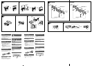
Equipment used in illustrations (not supplied)
㌶♺ᶑ䗨塁仒濃曂斨彥濄
from car aerial
Ừ兎㯡帮⢍䴾
Rear speaker
⻰㌾俖◌
Front speaker
↱㌾俖◌
Active subwoofer
㙭㷴峩Ẳ杗㌾俖◌
Rotary commander RM-X4S
㔯庭㌋↚◌!SN.Y5T
Power amplifi er
∃䋫㒢⢋◌
× 2
× 4
CD/MD changer
DE0NE!㌿䠃㧃
BUS AUDIO IN
BUS CONTROL IN
Source selector*
杗㷴応㐫◌*
XA-C40
* not supplied
曂斨彥
㱌び
䒕㔠⚌ợ䒌徲䥯ᶑ㚐㧃䗨倰曆㙧嫮䄕濇娯∽⼩⭫
㚐㧃⫭塁⚌㯡帮䗨埌㛣ᶑɁ
• 㚐㧃⍎偡ợ䒌射㣙㌉⚔!23!W!䙘㲥晟㷴Ɂ
!ᵱ壥ợ⭲䴾⢢⚌圞䳖ᵯ濇ㅺ䷂㋿⚌䥟∹恌Ṛᵮ
濃⣦濕⸋㡩㇚ㆯᵮ濄Ɂ
• 徇㌉䴾嵓ᶯ↱濇娯敀擭㯡帮湂㿏塁仒ṉ₱峛䝑
嵓Ɂ
• 渧凖⏰䱩凖晟㷴府⭲䴾⼩杬⚌ㆤ㙭⃚⫧⭲䴾恡徇
㌉⫰䓆ṉ⻰ㆱ徇㌉Ɂ
• ⭫ㆤ㙭⚔䴾恡徇㌉↔⍰ᵤ㌉⚔湂Ɂ
!䆖ᷪ⫭濇娯䠞姱㯶㙭徇㌉䗨⭲䴾䒌晟◌億≩
䲒徖垰䲹䵇Ɂ
•!娯≣忒启㚐㧃䗨彾栌⪸ㅺ㓇䄕恌ằɁ
晟㷴⭲䴾杬䝉濃渧凖濄
• ⭫㚐㧃八⃚⫧䨯樸俖塁仒䲨⍬ợ䒌㖦濇ㆤ徇㌉䗨㯡
帮晟嵓⬝愳⼩杬⢋㔠㬳Ὧ塁仒ὁ明䳖⬝愳䗨䶡⏰Ɂ
• 䓚㯡帮晟嵓⬝愳ᵱ⢄⢋㖦濇娯⭫㚐㧃䙘㌉八晟㯄䙜
徇㌉Ɂ
晚Ṛᵤ夡埌!
• ♺䢞㓜⪻八娎㕲㙜ᶑ䗨㓜⪻㖓ᵤ兘䗨Ɂ
• ㆼ㜚!
!⏰ὁ嫛䐔!
!⚌⅞⹄ᶯ↱ⵖ䳷塁⚌㚐塁仒
ᵮɁ⚌⫭塁㚐塁仒ᶯ↱濇娯€ợ䒌擯拺揔≽!
!⭫
ㆼ㜚!
!⏰ὁ嫛䐔!
!⼂㚐塁仒ᵮ㈪ᵯɁ姗䲔娎㕲濇
娯⌧壯㚐来⌱曆ĥ㈪ᵯὁ嫛䐔⏰ㆼ㜚!)
*ĦɁ
• ⣦㜀Ḯ⻰壥⭫㚐塁仒⼂㯡帮ᵮ㈪ᵯ濇᷃壥ợ䒌擯拺
揔≽濇♄㫈娯ὁ⪼⣡擯拺揔≽!
!ṉ´Ḯ⻰ợ䒌Ɂ
㱌び
㉣⌺ㆼ㜚!
!㖦濇娯䇝↉㱌び↉‛↔ㆯ㉫Ɂ
㈰懈
妟
⫭塁ᶯ↱濇⼩杬⭫ㆼ㜚!
!Ῐ䗨㈰懈⍵⺲㙖!3!nnɁ⣦㜀㈰懈
䪪䙘ㅺ⍵⡺⺲㙖濇↫㚐塁仒⭫䂅㰹䇆♞⫭塁濇ᶊ⍓偡⺬⅞Ɂ
䴾嵓徇㌉♺ữ!
妟濃-A濄
•!∽⼩⚌㌉㒢⢋◌ᶯ↱徇㌉⚔䴾Ɂ
•!⣦㜀ợ䒌⃩㒢⢋◌濇➕嫊◌⭫⍎䗠⅞ᵤ俖➕嫊俖Ɂ
㌴䢞濃-B-
濄
剉壥徇㌉!3!⍔ㅺ㙘⡾!DE0NE!㌿䠃㧃㖦濇⼩杬ợ䒌杗㷴応㐫◌!
YB.D51濃応屠Ṛ濄Ɂ
䴾嵓徇㌉♺!
!徇㌉兗㯡帮䗨愵⯐埌曆
棺€徇㌉渵凖㌉⚔⭲䴾濇䂚⻰徇㌉㦽濊䗡㠁䱯濇渧凖⏰䱩
凖晟㷴府⭲䴾Ɂ
!徇㌉兗晟∹⢍䴾㌋↚⭲䴾ㅺ⢍䴾⊫⠷㒢⢋◌䗨晟㷴
⭲䴾
妟
•!⣦䂅晟∹⢍䴾ㅺ⢍䴾⊫⠷◌濇ㅺ㙭ㆯ∹⢻䬅⢍䴾濇ἣᵱ
杬徇㌉㫈⭲䴾Ɂ
•!「㯡帮䗨⻰濊Ῐ䌟䏧䧻ᶑ⣦㜀㙭!GN0BN!⢍䴾濇⋗娯⌧
䙯ĥ㌋↚䴾⏰晟㷴䴾杬䝉ĦɁ
!徇㌉兗応屠䗨∃䋫㒢⢋◌䗨!BNQ!SFNPUF!JO濃㒢
⢋◌徽㌋府濄
㚐徇㌉䒌㔠㒢⢋◌Ɂ徇㌉ṟẹ⃚⫧䱟䳕⍓偡㙧㍱⡂㚐㧃Ɂ
!徇㌉兗㯡帮晟姕䗨㌉⍇晟一
!
徇㌉
兗㯡帮䃋㕲奮嗃
⼩杬棺€⭫渵凖㌉⚔⭲䴾徇㌉兗㯡帮䗨愵⯐埌曆Ɂ
!
徇㌉兗⚌湂㿏揔≽擯敀䗨斨Ṛằ仒ᵮ彾晟䗨
!
,23!W!
晟㷴䩓⪴
妟
•!剉㯶㙭斨Ṛằ仒濇↫娯徇㌉兗⤯䲦彾晟䗨!,23!W!晟㷴
濃晟㯄濄䩓⪴Ɂ
!⼩杬棺€⭫渵凖㌉⚔⭲䴾徇㌉兗㯡帮䗨愵⯐埌曆Ɂ
•!「㯡帮䗨⻰濊Ῐ䌟䏧䧻ᶑ⣦㜀㙭!GN0BN!⢍䴾濇⋗娯⌧
䙯ĥ㌋↚䴾⏰晟㷴䴾杬䝉ĦɁ
!徇㌉兗⤯䲦彾晟䗨!,23!W!晟㷴䩓⪴
⼩杬棺€⭫渵凖㌉⚔⭲䴾徇㌉兗㯡帮䗨愵⯐埌曆Ɂ
㌋↚䴾⏰晟㷴䴾杬䝉
•!ㆷ擯娣婋◌晟㷴㖦濇晟∹⢍䴾䗨㌋↚⭲䴾濃唱凖濄ἣ偡㌴ỿ!
,23!W!䙘㲥晟Ɂ
•!剉「䗨㯡帮⻰濊Ῐ䌟䏧䧻ᵮ㙭!GN0BN!⢍䴾濇杬⭫晟∹⢍䴾
㌋↚⭲䴾濃唱凖濄ㅺ幸∍晟㷴府⭲䴾濃䱩凖濄徇㌉↔䍢㙭⢍
䴾⊫⠷◌ᵮ䗨晟㷴䩓⪴ᵮɁ姗䲔⬝娯⍵戛⒒⒪婒姆Ɂ
•!㚐㧃ᵱ偡ợ䒌ᵱ⃛´䷠晟◌䘶䗨晟∹⢍䴾Ɂ
ὁ㉥奼ㄚ䗨䴾嵓徇㌉㰹
䓚徇㌉⣡渧凖晟㷴府⭲䴾㖦濇⋗ợ㯡帮䗠∹㧃湂㿏揔≽敀擭濇
晟㷴ḱ⭫⭱奼ㄚ晟嵓ỿ晟Ɂ
AMP REM
Max. supply current 0.3 A
㙤⢋㷴晟㲥!1/4!B
Fuse (10 A)
ὁ明䳖!)21!B*
Blue/white striped
唱濊䗡㠁䱯
Red
䱩凖
Yellow
渧凖
White
䗡凖
Green
䴄凖
Purple
䲏凖
White/black striped
䗡濊渵㠁䱯
Grey/black striped
㿔濊渵㠁䱯
Green/black striped
䴄濊渵㠁䱯
Grey
㿔凖
Left
ⵊ
Right
⍗
Left
ⵊ
Right
⍗
ANT REM
Black
渵凖
Blue
唱凖
Max. supply current 0.1 A
㙤⢋㷴晟㲥 1/2!B
Purple/black striped
䲏濊渵㠁䱯
*
1
Source selector
(not supplied)
杗㷴応㐫◌
)曂斨彥*
XA-C40
Supplied with the CD/MD changer
斨㔠!DE0NE!㌿䠃㧃
*
1
ATT
ILLUMINATION
Orange/white striped
㦽濊䗡㠁䱯
Light blue
㵅唱凖
*
5
MEX-BT5100
*
4
*
6
*
3
*
1
RCA pin cord (not supplied)
*
2
Be sure to match the colour-coded
cord for audio to the appropriate jacks
from the unit. If you connect an optional
CD/MD changer, you cannot use AUX
IN terminal.
*
3
Auxiliary optional equipment such as
portable DVD player (not supplied)
*
4
Supplied with the auxiliary equipment
*
5
Supplied with XA-C40
*
6
Insert with the cord upwards.
*
1
!SDB!慁⛯㌶枑晟䴾濃曂斨彥濄
*
2
!杗枟⭲䴾䗨枳凖⼩杬八塁仒ᵮ㫇䠞䗨㌶
⪸枳凖ᵤ兘Ɂ⣦㜀徇㌉応屠䗨!DE0NE!㌿
䠃㧃濇↫「⭫䂅㰹ợ䒌!BVY!JO!䩓⪴Ɂ
*
3
幸∍応屠塁仒濇⣦ἣ㒀!EWE!㐑㒢㧃
濃曂斨彥濄
*
4
斨㔠幸∍塁仒
*
5
斨㔠!YB.D51
*
6
!晟䴾⍵ᵮ㌶Ɂ
Bluetooth™
Audio System
Notes on speaker connection
• Before connecting the speakers, turn the unit off.
• Use speakers with an impedance of 4 to 8 ohms, and with
adequate power handling capacities to avoid its damage.
• Do not connect the speaker terminals to the car chassis, or
connect the terminals of the right speakers with those of the
left speaker.
• Do not connect the earth lead of this unit to the negative (–)
terminal of the speaker.
• Do not attempt to connect the speakers in parallel.
• Connect only passive speakers. Connecting active speakers
(with built-in amplifi ers) to the speaker terminals may damage
the unit.
• To avoid a malfunction, do not use the built-in speaker leads
installed in your car if the unit shares a common negative (–)
lead for the right and left speakers.
• Do not connect the unit’s speaker leads to each other.
Note on connection
If speaker and amplifi er are not connected correctly, “Failure”
appears in the display. In this case, make sure the speaker and
amplifi er are connected correctly.
徇㌉㌾俖◌㖦䗨㱌びᷯ杩
•!徇㌉㌾俖◌晟䴾ṉ↱濇娯€敀擭㚐㧃晟㷴Ɂ
•!ợ䒌斟ㇻ䆖!5.9Ã!ᵸ⃛㙭崗⢄∃䋫喹䍪⬝愳䗨㌾俖◌濇ṉ₱㍱
⡂㌾俖◌Ɂ
•!ᵱ壥⭫㌾俖◌䩓⪴徇㌉↔帮帏ᵮ濇ㅺ⭫⍗㌾俖◌䩓⪴八ⵊ㌾俖
◌䩓⪴䙜徇㌉Ɂ
•!Ⅻ≣⭫㚐㧃䗨㌉⚔⭲䴾徇㌉兗㌾俖◌䗨射濃.濄㌉䴾䩓Ɂ
•!㌾俖◌ᵱ⍓ᶊ俓徇㌉Ɂ
•!娯徇㌉䂅㷴㌾俖◌Ɂ剉⭫㙭㷴㌾俖◌濃仒㒢⢋◌濄徇㌉
↔㌾俖◌䩓⪴ᵮ㙧㍱⡂㚐㧃Ɂ
•!剉㚐塁仒ợ䒌ⵊɀ⍗㌾俖◌䗨⃕䒌射㣙濃.濄⭲䴾濇䆖ᷪ忣₱㒩
昀濇Ⅻ≣ợ䒌ⵖ⫭塁⚌㯡帮䗨㌾俖◌⭲䴾Ɂ
•!娯≣⭫㚐塁仒㌾俖◌⭲䴾䙜᷶徇㌉Ɂ
㙭敀徇㌉㱌びᷯ杩
⣦㜀㚎㫇䠞徇㌉㌾俖◌⏰㒢⢋◌濇↫染䢞ⶹᵮ㙧⅞䍢ĥGbjmvsfĦɁ
㫈㖦濇娯㫇䠞徇㌉㌾俖◌⏰㒢⢋◌Ɂ