


4
(GB)
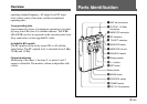
Parts Identification
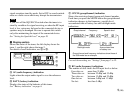
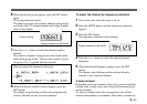
the squelch level setting.
When the squelch level is set to 5 dBµ;
On in green: RF input is more than 15 dBµ.
On in red: RF input is between 5 dBµ and 15 dBµ.
Off: RF input is less than 5 dBµ.
When the squelch level is set to 10 dBµ;
On in green: RF input is more than 20 dBµ.
On in red: RF input is between 10 dBµ and 20 dBµ.
Off: RF input is less than 10 dBµ.
When the squelch level is set to 15 dBµ;
On in green: RF input is more than 25 dBµ.
On in red: RF input is between 15 dBµ and 25 dBµ.
Off: RF input is less than 15 dBµ.
5 TX BATT (transmitter battery) indicators
Show the battery conditions of the two wireless microphone
transmitters independently. The indicators start flashing
about one hour before the transmitter batteries go flat.
6 MONITOR switch
Select the tuner to monitor. The “1+2” position allows to
monitor the mixed output of both tuners.
7 MONITOR volume
Turn to adjust the monitoring level through headphones.
8 SQUELCH switch
In ordinary use, set the switch to ON, and the noise and
signal interference will be eliminated when the tuner is in
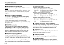
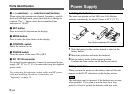
1 ANT (antenna) a/b connectors
Connect the antennas supplied to both ANT a/b connectors.
Note
Be sure to connect two antennas to these connectors, even
when you use one tuner, to make the diversity reception
properly.
2 OUTPUT 1/2 (BAL) connectors
The OUTPUT 1 connector supplies audio signal output
from tuner 1, and the OUTPUT 2 connector supplies the
output from tuner 2.
Connect these connectors to the microphone input
connector of a camcorder, mixer, or tape recorder by using
the supplied cable.
3 MONITOR connector
To monitor the tuner output, connect the headphones,
equipped with a 3.5 mm (
5
/32
inch) dia stereo mini jack.
Use either of stereo or monaural headphones. Select the
tuner to be monitored with the MONITOR switch, and
adjust the monitor level with the MONITOR volume.
4 RF (radio frequency) indicators
Indicate the strength of the RF input signal and the
receiving antenna for diversity reception of each tuner; the
left pair is for the tuner 1, and the right pair is for the tuner
2.
The indication color shows the strength of the RF input
signal. The indicated signal level changes corresponding to