


XR-4950X
2424
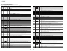
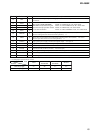
6-9. IC PIN FUNCTION DESCRIPTION
• MAIN BOARD IC501 MN101C49KTA2 (SYSTEM CONTROLLER)
Pin No. Pin Name I/O Description
1 VREF I Reference voltage (0V) input terminal (for A/D converter)
2 VSM I
FM and AM signal meter voltage detection input from the FM/AM tuner unit (TU1)
(A/D input)
3 FMAGC I FM AGC level detection signal input from the FM/AM tuner unit (TU1) (A/D input)
4 KEYIN1 I
Key input terminal (A/D input) (LSW801, LSW909, LSW912 to LSW917)
Z, D-BASS, 6, 5, 4, 3, 2, REP 1 keys input
5 KEYIN0 I
Key input terminal (A/D input) (LSW901 to LSW907, S901 to S904)
OFF, SOURCE, SOUND, MENU, MODE o, ENTER, SEEK/AMS – . m,PRST +,
SEEK/AMS + > M, PRST – keys input
6 DSTSEL I Destination setting terminal (fixed at “H” in this set)
7 RCIN0 I Rotary remote commander key input terminal (A/D input)
8 QUALITY I Noise level detection signal input at SEEK mode (A/D input) Not used (open)
9 — O Not used (open)
10 VREF I Reference voltage (+5V) input terminal (for A/D converter)
11 VDD — Power supply terminal (+5V) (for A/D converter)
12 OSCOUT O Main system clock output terminal (18.432 MHz)
13 OSCIN I Main system clock input terminal (18.432 MHz)
14 VSS — Ground terminal (for A/D converter)
15 XIN I Sub system clock input terminal (32.768 kHz)
16 XOUT O Sub system clock output terminal (32.768 kHz)
17 MMOD I Not used (fixed at “L”)
18 NOSESW I
Front panel block remove/attach detection signal input
“L”: front panel is attached, “H”: front panel is removed
19 BUSON O Bus on/off control signal output terminal “L”: bus on Not used (fixed at “H”)
20 SYSRST O Reset signal output terminal “L”: reset Not used (fixed at “H”)
21 LCDSO O Serial data output to the liquid crystal display driver (IC901)
22 LCDCE O Chip enable signal output to the liquid crystal display driver (IC901) “H” active
23 LCDCKO O Serial data transfer clock signal output to the liquid crystal display driver (IC901)
24 RCIN1 I Rotary remote commander shift key input terminal “L”: shift
25 RAMBU I
Internal RAM reset detection signal input terminal
Input terminal to check that RAM data are not destroyed due to low voltage
This checking is made within 50 msec after reset Not used (fixed at “L”)
26 KEYACK I
Input of acknowledge signal for the key entry Acknowledge signal is input to accept function
and eject keys in the power off status On at input of “H”
27 — O Not used (open)
28 BUIN I Battery detect signal input from the battery detect circuit “L” is input at low voltage
29 SIRCS I Sircs remote control signal input terminal Not used (fixed at “L”)
30, 31 — O Not used (open)
32 MTLIN I Auto metal detection signal input terminal “H”: auto metal Not used (fixed at “L”)
33 RESET I
System reset signal input from the reset signal generator (IC551) and reset switch (S551)
“L”: reset “L” is input for several 100 msec after power on, then it changes to “H”
34 TUNON O
Tuner system power supply on/off control signal output to the BA4908 (IC611)
“H”: tuner power on
35 BEEP O Beep sound drive signal output to the power amplifier (IC751)
36 PW ON O
Main system power supply on/off control signal output to the BA4908 (IC611)
“H”: power on
37 COLSEL I Setting terminal for the illumination color “L”: amber, “H”: green Fixed at “L” in this set
Pin No. Pin Name I/O Description
38 ACC IN I Accessory detection signal input “L”: accessory on
39 TESTIN I Setting terminal for the test mode “H”: test mode, Normally: fixed at “L”
40 TELATT I Telephone muting signal input terminal At input of “H”, the signal is attenuated by –20 dB
41 UNICLI I Serial data transfer clock signal input terminal Not used (fixed at “L”)
42 UNISO O Serial data output terminal Not used (fixed at “L”)
43 UNISI I Serial data input terminal Not used (fixed at “L”)
44 UNICKO O Serial data transfer clock signal output terminal Not used (fixed at “L”)
45 I2C SIO I/O Two-way data bus with the electrical volume (IC331) and FM/AM tuner unit (TU1)
46 VOLATT O Muting on/off control signal output to the electrical volume (IC331) “L”: muting on
47 I2C CKO O Clock signal output to the electrical volume (IC331) and FM/AM tuner unit (TU1)
48 AMPON O
Standby on/off control signal output to the power amplifier (IC751)
“L”: standby mode, “H”: amplifier on
49 AMPATT O Muting on/off control signal output to the power amplifier (IC751) “L”: muting on
50 ATT O Audio line muting on/off control signal output “H”: muting on
51 TU ATT O
Muting on/off control signal output of the FM and AM tuner signal “H”: muting on
Not used (open)
52 AMSON O
Tape auto music sensor control signal output to the CXA2509AQ (IC301)
“L” is output to lower the gain for audio level at FF/REW mode
53 NROUT O
Forward/reverse direction control signal output to the CXA2509AQ (IC301)
“L”: forward direction, “H”: reverse direction
54 MTLON I/O
METAL control in/out terminal
At initial mode: auto/manual mode selection input of METAL function (manual at “L” input)
At manual mode: METAL on/off control signal output terminal (METAL on at “H” output)
At auto mode: input at MTLIN (pin es)
55 TAPATT O
Tape muting on/off control signal output to the CXA2509AQ (IC301) “H”: muting on
Active at ATA, FF/REW mode
56 DOLON I/O
Dolby control in/out terminal
At initial mode: valid/invalid selection input of dolby function (valid at “L” input)
At normal mode: dolby on/off control signal output terminal (dolby on at “H” output)
Not used this function (fixed at “H”)
57 AMSIN I
Whether a music is present or not from CXA2509AQ (IC301) is detected at auto music sensor
“L”: music is present, “H”: music is not present
58 4VPRE I 4VPREOUT model setting terminal “L”: 4VPREOUT model Fixed at “H” in this set
59 to 73 — O Not used (open)
74 E2P SIO I/O Two-way data bus with the FM/AM tuner unit (TU1)
75 E2P CKO O Clock signal output to the FM/AM tuner unit (TU1)
76 — O Not used (open)
77 SWSHIFT O AM filter control signal output to the FM/AM tuner unit (TU1) “L”: SW mode
78 DOORSW I Front panel open/close detection signal input “L” is input when the front panel is closed
79 DOORIND O
LED drive signal output of the tape window and Z indicator (LED801, LSW801)
“H”: LED on “H” is output to turn on LED when front panel is opened
80 REIN1 I
81 REIN0 I
82 AD ON O
A/D converter power control signal output
When the KEYACK (pin wh) that controls reference voltage power for key A/D conversion input
is active, “L” is output from this terminal to enable the input
83 ILLON O
Power on/off control signal output of the illumination LED and liquid crystal display driver
(IC901) “H”: power on
Dial pulse input of the rotary encoder (RE901) (for volume control)